|
|
| Line 48: |
Line 48: |
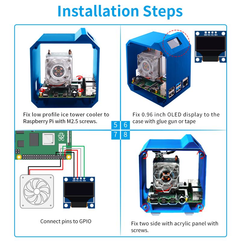
| 0.96 inch OLED usage please refer to: [ https://wiki.52pi.com/index.php/S-0005 ] | | 0.96 inch OLED usage please refer to: [ https://wiki.52pi.com/index.php/S-0005 ] |
| After installing ssd1306 driver, you can refer to the example code to create your own python script to show system informations. | | After installing ssd1306 driver, you can refer to the example code to create your own python script to show system informations. |
| ===Method 2 ===
| |
| * This method will refer to Adafruit python SSD1306 example for this display.
| |
| Open a terminal and Download demo code from: [ https://github.com/adafruit/Adafruit_Python_SSD1306 ]
| |
| <pre>
| |
| sudo python3 -m pip install --upgrade pip setuptools wheel
| |
| git clone https://github.com/adafruit/Adafruit_Python_SSD1306.git
| |
| cd Adafruit_Python_SSD1306
| |
| sudo python setup.py install
| |
| pip3 install Adafruit-BBIO
| |
| pip3 install Adafruit_GPIO
| |
| pip3 install Adafruit_SSD1306
| |
| pip3 install smbus2
| |
| pip3 install pi-ina219
| |
| </pre>
| |
| * Run example Demo:
| |
| <pre>
| |
| cd examples/
| |
| </pre>
| |
| * You may need to modify the stats.py as following code:
| |
| <pre>
| |
|
| |
| import time
| |
|
| |
| import Adafruit_GPIO.SPI as SPI
| |
| import Adafruit_SSD1306
| |
|
| |
| from PIL import Image
| |
| from PIL import ImageDraw
| |
| from PIL import ImageFont
| |
|
| |
| import subprocess
| |
| import smbus2
| |
| from ina219 import INA219, DeviceRangeError
| |
|
| |
| # Raspberry Pi pin configuration:
| |
| RST = None # on the PiOLED this pin isnt used
| |
| # Note the following are only used with SPI:
| |
| DC = 23
| |
| SPI_PORT = 0
| |
| SPI_DEVICE = 0
| |
| DEVICE_BUS = 1
| |
|
| |
| DEVICE_ADDR = 0x17
| |
| PROTECT_VOLT = 3700
| |
| SAMPLE_TIME = 2
| |
|
| |
| ina_supply = INA219(0.00725, address=0x40)
| |
| ina_supply.configure()
| |
| supply_voltage = ina_supply.voltage()
| |
| supply_current = ina_supply.current()
| |
| supply_power = ina_supply.power()
| |
|
| |
| ina_batt = INA219(0.005, address=0x45)
| |
| ina_batt.configure()
| |
| batt_voltage = ina_batt.voltage()
| |
| batt_current = ina_batt.current()
| |
| batt_power = ina_batt.power()
| |
|
| |
|
| |
| # Beaglebone Black pin configuration:
| |
| # RST = 'P9_12'
| |
| # Note the following are only used with SPI:
| |
| # DC = 'P9_15'
| |
| # SPI_PORT = 1
| |
| # SPI_DEVICE = 0
| |
|
| |
| # 128x32 display with hardware I2C:
| |
| # disp = Adafruit_SSD1306.SSD1306_128_32(rst=RST) ####### please comment this line by adding hash tag in front of line #######
| |
|
| |
| # 128x64 display with hardware I2C: ##########################Please Open following line by removing hash tag ######
| |
| disp = Adafruit_SSD1306.SSD1306_128_64(rst=RST)
| |
|
| |
| # Note you can change the I2C address by passing an i2c_address parameter like:
| |
| # disp = Adafruit_SSD1306.SSD1306_128_64(rst=RST, i2c_address=0x3C)
| |
|
| |
| # Alternatively you can specify an explicit I2C bus number, for example
| |
| # with the 128x32 display you would use:
| |
| # disp = Adafruit_SSD1306.SSD1306_128_32(rst=RST, i2c_bus=2)
| |
|
| |
| # 128x32 display with hardware SPI:
| |
| # disp = Adafruit_SSD1306.SSD1306_128_32(rst=RST, dc=DC, spi=SPI.SpiDev(SPI_PORT, SPI_DEVICE, max_speed_hz=8000000))
| |
|
| |
| # 128x64 display with hardware SPI:
| |
| # disp = Adafruit_SSD1306.SSD1306_128_64(rst=RST, dc=DC, spi=SPI.SpiDev(SPI_PORT, SPI_DEVICE, max_speed_hz=8000000))
| |
|
| |
| # Alternatively you can specify a software SPI implementation by providing
| |
| # digital GPIO pin numbers for all the required display pins. For example
| |
| # on a Raspberry Pi with the 128x32 display you might use:
| |
| # disp = Adafruit_SSD1306.SSD1306_128_32(rst=RST, dc=DC, sclk=18, din=25, cs=22)
| |
|
| |
| # Initialize library.
| |
| disp.begin()
| |
|
| |
| # Clear display.
| |
| disp.clear()
| |
| disp.display()
| |
|
| |
| # Create blank image for drawing.
| |
| # Make sure to create image with mode '1' for 1-bit color.
| |
| width = disp.width
| |
| height = disp.height
| |
| image = Image.new('1', (width, height))
| |
|
| |
| # Get drawing object to draw on image.
| |
| draw = ImageDraw.Draw(image)
| |
|
| |
| # Draw a black filled box to clear the image.
| |
| draw.rectangle((0,0,width,height), outline=0, fill=0)
| |
|
| |
| # Draw some shapes.
| |
| # First define some constants to allow easy resizing of shapes.
| |
| padding = -2
| |
| top = padding
| |
| bottom = height-padding
| |
| # Move left to right keeping track of the current x position for drawing shapes.
| |
| x = 0
| |
|
| |
|
| |
| # Load default font.
| |
| font = ImageFont.load_default()
| |
|
| |
| # Alternatively load a TTF font. Make sure the .ttf font file is in the same directory as the python script!
| |
| # Some other nice fonts to try: http://www.dafont.com/bitmap.php
| |
| # font = ImageFont.truetype('Minecraftia.ttf', 8)
| |
|
| |
|
| |
| # i2c bus configure
| |
| bus = smbus2.SMBus(DEVICE_BUS)
| |
| aReceivedBuf = []
| |
| aReceivedBuf.append(0x00)
| |
|
| |
| for i in range(1, 255):
| |
| aReceivedBuf.append(bus.read_byte_data(DEVICE_ADDR, i))
| |
|
| |
| while True:
| |
|
| |
| # Draw a black filled box to clear the image.
| |
| draw.rectangle((0,0,width,height), outline=0, fill=0)
| |
|
| |
| # Shell scripts for system monitoring from here : https://unix.stackexchange.com/questions/119126/command-to-display-memory-usage-disk-usage-and-cpu-load
| |
| cmd = "hostname -I | cut -d\' \' -f1"
| |
| IP = subprocess.check_output(cmd, shell = True )
| |
| cmd = "top -bn1 | grep load | awk '{printf \"CPU Load: %.2f\", $(NF-2)}'"
| |
| CPU = subprocess.check_output(cmd, shell = True )
| |
| cmd = "free -m | awk 'NR==2{printf \"Mem: %s/%sMB %.2f%%\", $3,$2,$3*100/$2 }'"
| |
| MemUsage = subprocess.check_output(cmd, shell = True )
| |
| cmd = "df -h | awk '$NF==\"/\"{printf \"Disk: %d/%dGB %s\", $3,$2,$5}'"
| |
| Disk = subprocess.check_output(cmd, shell = True )
| |
|
| |
| aReceivedBuf = []
| |
| aReceivedBuf.append(0x00)
| |
|
| |
| for i in range(1, 255):
| |
| aReceivedBuf.append(bus.read_byte_data(DEVICE_ADDR, i))
| |
|
| |
| batt_voltage = ina_batt.voltage()
| |
| batt_current = ina_batt.current()
| |
| batt_power = ina_batt.power()
| |
| if (aReceivedBuf[8] << 8 | aReceivedBuf[7]) > 4000:
| |
| charge_port = 'Charging via Type-C'
| |
| elif (aReceivedBuf[10] << 8 | aReceivedBuf[9]) > 4000:
| |
| charge_port = 'Charging via MicroUSB'
| |
| else:
| |
| charge_port = 'Not Charging'
| |
|
| |
| # Write two lines of text.
| |
|
| |
| draw.text((x, top), "IP: " + str(IP.decode('utf-8')), font=font, fill=255)
| |
| draw.text((x, top+8), str(CPU.decode('utf-8')), font=font, fill=255)
| |
| draw.text((x, top+16), str(MemUsage.decode('utf-8')), font=font, fill=255)
| |
| draw.text((x, top+25), str(Disk.decode('utf-8')), font=font, fill=255)
| |
|
| |
| # Display image.
| |
| disp.image(image)
| |
| disp.display()
| |
| time.sleep(3)
| |
|
| |
| draw.rectangle((0,0,width,height), outline=0, fill=0)
| |
| draw.text((x, top),"Voltage: " + str(batt_voltage), font=font, fill=255)
| |
| draw.text((x, top+8), "Current:" + str(batt_current), font=font, fill=255)
| |
| draw.text((x, top+16),"Power:" + str(batt_power), font=font, fill=255)
| |
| draw.text((x, top+25),"CHRGPort:" + str(charge_port), font=font, fill=255)
| |
| # display UPS information
| |
|
| |
| disp.image(image)
| |
| disp.display()
| |
| time.sleep(3)
| |
| </pre>
| |
| * Then execute following command:
| |
| <pre>
| |
| python3 stats.py
| |
| </pre>
| |
|
| |
| ===Method 3=== | | ===Method 3=== |
| ## How to enable OLED 0.96 | | ## How to enable OLED 0.96 |
