KR-0027
MicroBit Basic Starter Kit
Description
The Microbit Basic Starter Kit is an all-in-one package designed to introduce beginners to the world of electronics and programming. With a wide range of components and accessories, this kit provides an excellent platform for learning and creating exciting projects. Whether you're a student, hobbyist, or educator, the Microbit Basic Starter Kit is perfect for getting started with microcontroller-based projects.
About MicroBit
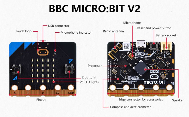
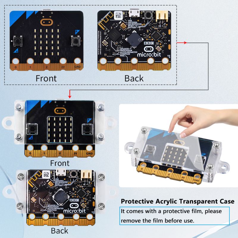
The Microbit board integrates commonly used sensor devices such as acceleration sensor, magnetic sensor, two programmable buttons, 25 single-color LEDs, and Bluetooth. Microbit uses a MicroUSB interface for power supply, and can be connected to an external battery box. There are also multiple golden finger pins at the bottom of the motherboard, which are convenient for external control devices. Whether it is a robot or a musical instrument, Microbit can realize any cool gizmo. You can use Microbit to write video games, realize sound and light interaction, do scientific experiments, control small robots, and calculate math problems, etc.
Microbit supports graphical or python programming, and supports almost all PCs and mobile devices.
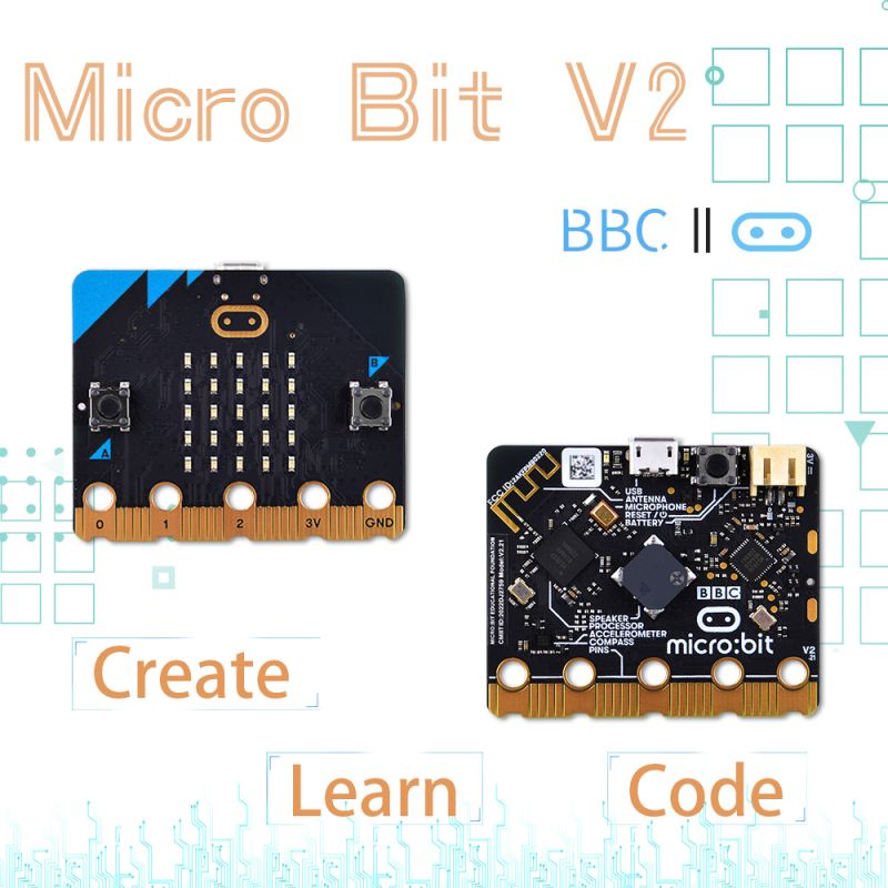
Different between V1 and V2
Microbit V1 and Microbit V2 are different versions of the Microbit development board. Here are some of the key differences between the two versions:
- Processor: Microbit V1 is powered by the Nordic nRF51822 system-on-a-chip (SoC) with a 16MHz ARM Cortex-M0 processor, while Microbit V2 features the Nordic nRF52833 SoC with a 64MHz ARM Cortex-M4 processor. The upgraded processor in Microbit V2 offers improved performance and capabilities.
- Memory: Microbit V1 has 16KB of RAM and 256KB of flash memory, whereas Microbit V2 has 128KB of RAM and 512KB of flash memory. The increased memory in Microbit V2 allows for more complex programs and larger storage capacity.
- Power Management: Microbit V2 includes enhanced power management features, allowing for more efficient energy usage and longer battery life. It also supports a wider voltage range for power supply options.
- Display: Both Microbit V1 and V2 have a 5x5 LED matrix display, but the display on Microbit V2 is brighter and clearer, providing better visibility in different lighting conditions.
- Sensors: Microbit V2 has additional sensors compared to Microbit V1. It includes a microphone and a speaker, enabling sound-related projects and applications.
- Connectivity: Microbit V2 offers improved wireless connectivity with Bluetooth 5.1, allowing for faster and more stable communication between devices.
- Edge Connector: The edge connector on Microbit V2 has been redesigned and expanded, providing more I/O pins for connecting external components and accessories.
It's important to note that while Microbit V2 offers several enhancements over Microbit V1, both versions are compatible with the Microbit coding platform and can be used for learning and creating projects. The choice between the two versions depends on specific requirements and preferences.
Features
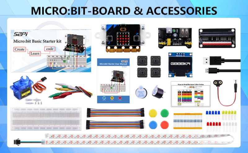
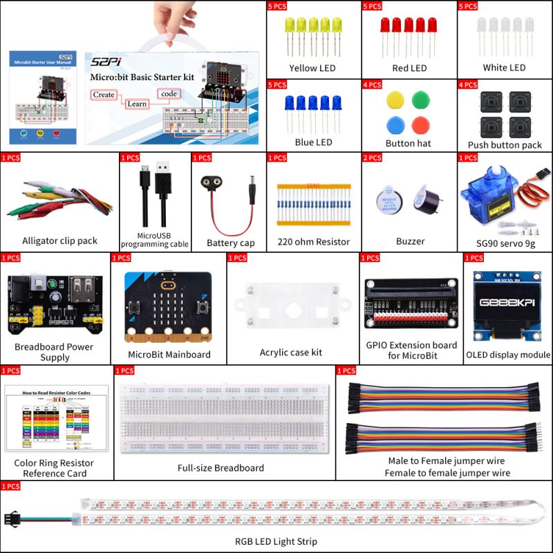
- Comprehensive Components: The kit includes a MicroBit development board, red, white, yellow, and blue LEDs, buttons with caps, crocodile clips, a 9V battery connector, a 220-ohm resistor, a buzzer, a 9g SG90 servo motor, a breadboard power module, an acrylic case, a MicroBit GPIO extension board, a 0.96-inch OLED screen, a color ring resistor color card, a full-size breadboard, an RGB LED strip, and male-to-male and male-to-female DuPont wires. These components allow for a wide range of circuit experiments.
- Beginner-Friendly: The kit is designed with beginners in mind. It provides clear and concise documentation, making it easy for anyone to get started with electronics and programming. No prior experience is required, and the kit guides users through step-by-step projects to build their knowledge and skills.
- Versatile Learning Platform: The Microbit Basic Starter Kit is a versatile learning platform that combines hardware and software. It utilizes the MicroBit development board, which is equipped with various sensors and peripherals, to enable a wide range of projects. From simple LED blinking to more advanced robotics and IoT applications, this kit offers endless possibilities for exploration and creativity.
Gallery
- Acrylic case and microbit details
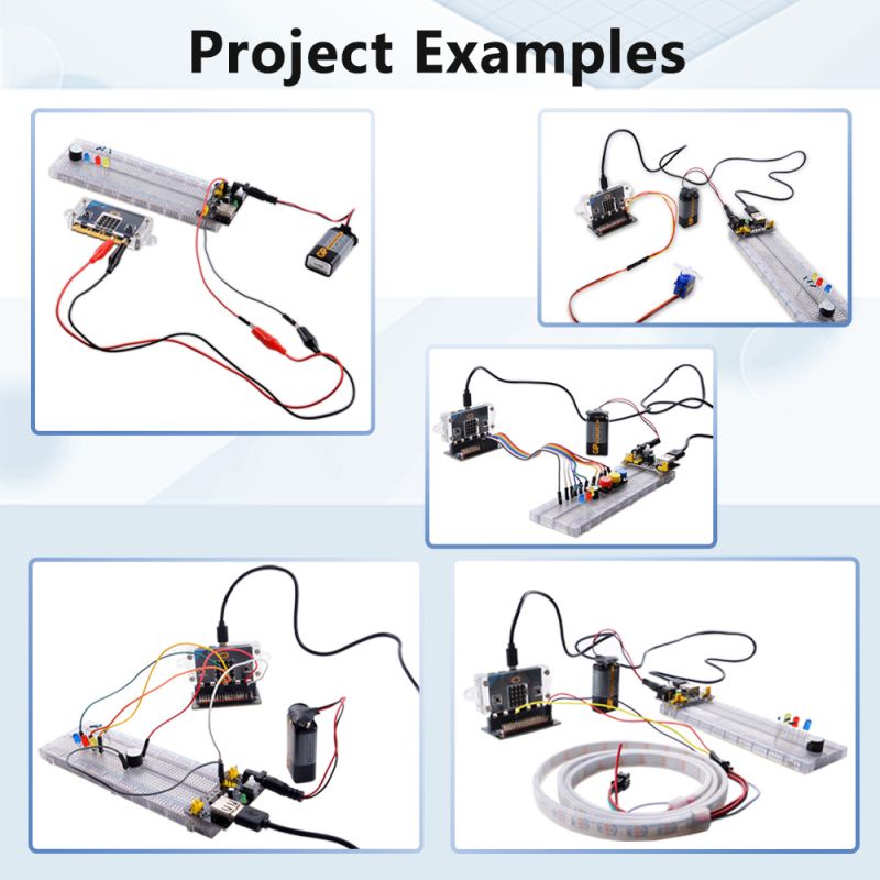
- Projects Examples
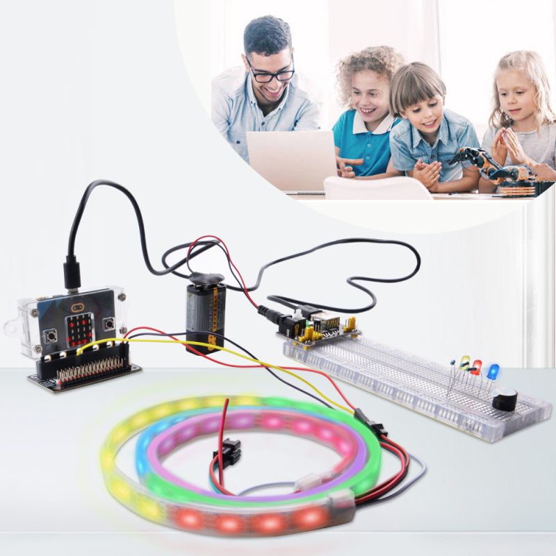
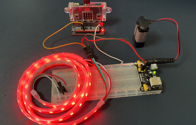
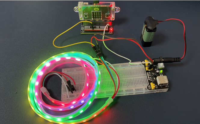
- Fancy LED light Strip
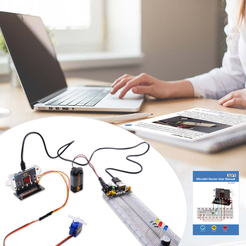
- Programming and coding
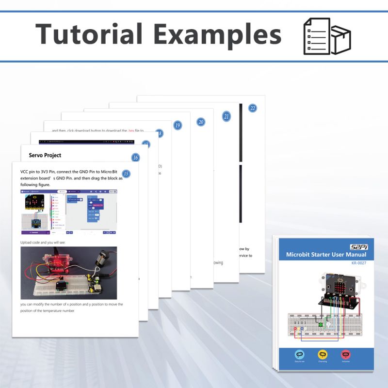
- Tutorial Examples
Getting Started
To begin your journey with the Microbit Basic Starter Kit, follow these steps:
- Familiarize yourself with the components: Take a look at the components included in the kit and understand their functions. The documentation provided will help you identify each component and its purpose.
- Set up your MicroBit development board: Connect the MicroBit board to your computer using a USB cable and install the necessary drivers. The documentation will guide you through this process.
- Explore the provided projects: The kit comes with a set of beginner-friendly projects that gradually introduce you to different concepts and functionalities. Start with the basic projects and work your way up to more complex ones.
- Experiment and create your own projects: Once you feel comfortable with the basics, start experimenting with different components and circuits. Combine sensors, LEDs, and other peripherals to create your own unique projects. The possibilities are endless!
Remember, the Microbit Basic Starter Kit is designed to encourage hands-on learning and creativity. Don't be afraid to explore, make mistakes, and learn from them. Have fun and enjoy your journey into the exciting world of electronics and programming!
MicroBit Specifications
- Width/Height: 5x4cm
- Weight: 9.0g
Technical Parameters
- Working voltage: 3V
- Output current: 40ma
- Power supply mode: MicroUSB interface for power supply, or use Micro bit’s 3V battery box interface for power supply
- Program download: use the MicroUSB data cable to download the program
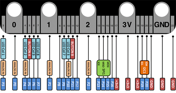
- Pin out: The control pins are out through the gold fingers at the bottom, including an I2C, an SPI, and serial ports through the IO port. (The I2C function pins are 19 and 20, these two pins cannot be used as ordinary IO to read and write, only for I2C communication)
- On-board components: three-axis accelerometer, magnetometer, 3 physical buttons (A/B/reset), 5x5 dot matrix screen (25 LED lights), Bluetooth/2.4G communication, temperature detection (inside the Bluetooth chip), light Intensity detection (reverse diode current)
Functional module
- Programmable LED screen
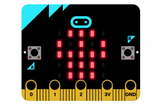
25 red LED lights form a 5x5 dot matrix, which can display various graphics. When programming the LED screen, you can choose to use the official built-in graphics library, such as various emoticons, or you can design your own graphics on the screen show
- Programmable keys
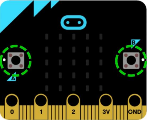
There are two programmable keys A and B on the front of the Microbit. The programming languages supported by the Microbit contain control blocks or commands for these two keys. The three key states can be detected through the program.
- Gold finger pin
Microbit golden finger pins include 19 configurable GPIOs, namely: P3, P0, P4-P7, P1, P8-P12, P2, P13-P16, 3V (3), P19-P20, GND (3). P5 and P11 are used to control the A and B keys of the motherboard.
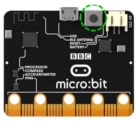
- Reset button
There is a reset button on the back of the Microbit. When the program needs to be restarted, press the reset button, and the downloaded program will run from the beginning.
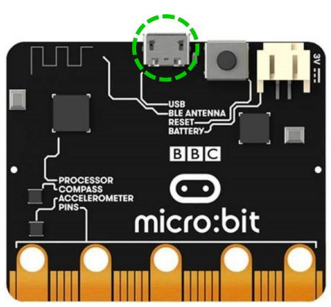
- USB Port
There is a MicroUSB interface on the back of the Microbit, which is mainly used to download the control program and supply power to the motherboard. When downloading a program, the micro
One end of the data cable of the USB interface is connected to the USB interface of the computer, and the other end is connected to the USB of Microbit.
Programming
You tell computers like the micro:bit what to do by giving them instructions. Sets of instructions for computers are called programs. Programs are written in code, a language that both you and the computer can understand. You can program your micro:bit in the online MakeCode block or Python text editors. Our Let's code page helps you choose the one that's right for you.
- a computer with a web browser and internet access
or
- a phone or tablet and our free micro:bit app for MakeCode coding on Android or iOS (iPhone and iPad) mobile devices
When you've written your code, you'll want to connect and transfer it onto the micro:bit.
Connect
- Connect your micro:bit to your computer or mobile device.
If you're using a computer, you need a micro USB cable to connect to your micro:bit to your computer's USB socket If you're using a phone or tablet, use Bluetooth to connect your micro:bit wirelessly.
- Transfer from a computer
Transferring your program to your micro:bit is called flashing because it copies your program into the micro:bit’s flash memory. Your micro:bit will pause and the yellow LED on the back will blink while your program is being transferred. Once it’s copied across, your program starts running on your micro:bit. There are two ways to transfer your program from a computer:
- Drag and drop is like copying a downloaded file from your computer to a USB memory stick. It works on any computer.
- Direct flashing sends your program from the code editor direct to your micro:bit. It works on any computer in two popular web browsers.
When you plug the micro:bit into your computer's USB socket, it will appear on your computer like a USB memory stick called MICROBIT. Download your program as a .hex file from the code editor to your computer, usually to your downloads folder. Then drag and drop the .hex file on to the MICROBIT drive. After you transfer your .hex file, the MICROBIT drive will disconnect and reconnect as the micro:bit resets. The .hex file will not be listed on the MICROBIT drive after this. This is expected. Your micro:bit is not a flash storage device, but your computer shows it as one to make it easy to transfer .hex files.
- More Details Please visit this URL online: [ https://microbit.org/get-started/first-steps/set-up/ ]
We have prepared several demo codes for you, and it is very easy to use to download to your microbit, just according to following steps to download demo codes to your microbit.
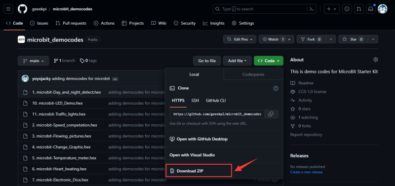
- 1. Download demo codes from GitHub【IMPORTANT】:
https://github.com/geeekpi/microbit_democodes
Download and unzip it.
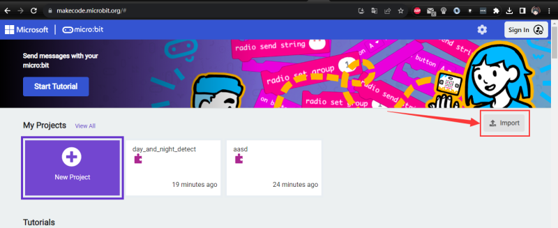
- 2. Open a browser and typing following URL:
https://makecode.microbit.org/#editor
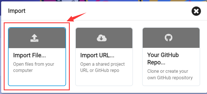
Import a project:
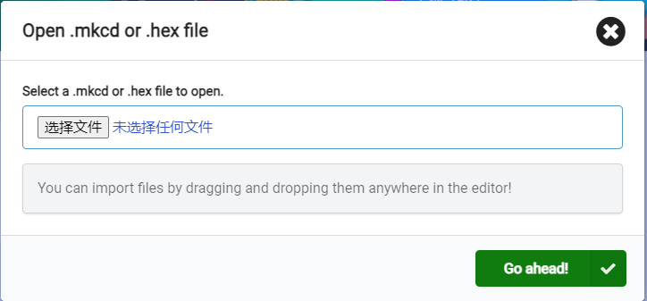
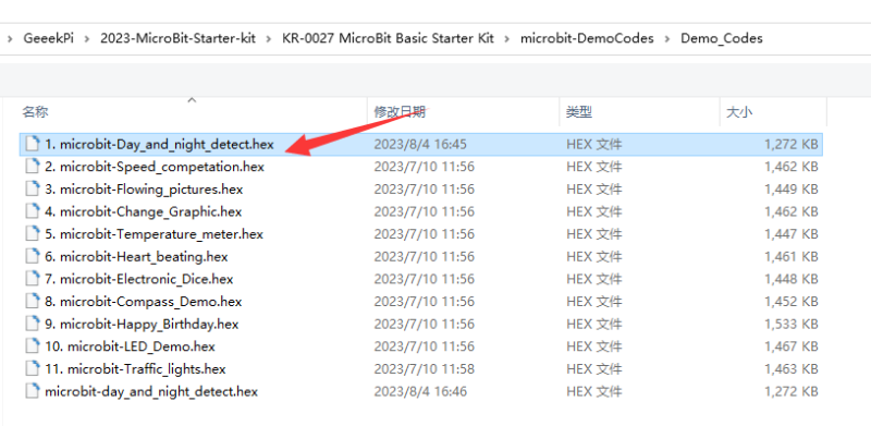
select .hex file that you’ve downloaded before.
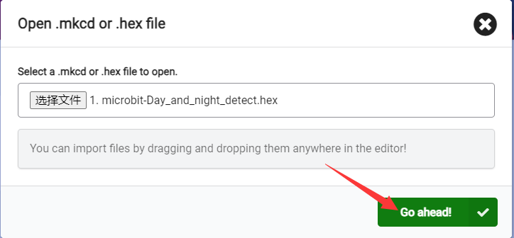
and then click Go ahead.
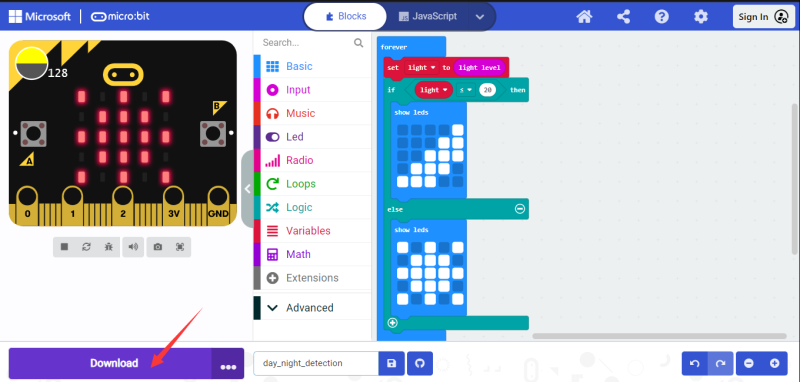
You will see the project, and next step is to connect the microbit to your PC via MicroUSB cable and click download button to download the demo code. Please check the Pin number or just modify the demo code to fit your current environment.
How to add extensions for Micro:Bit?
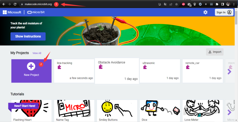
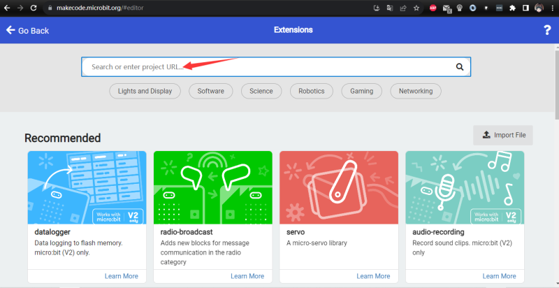
- 1. Open browser and input following URL: [1]
- 2. Click “New Project” icon to start a new project.
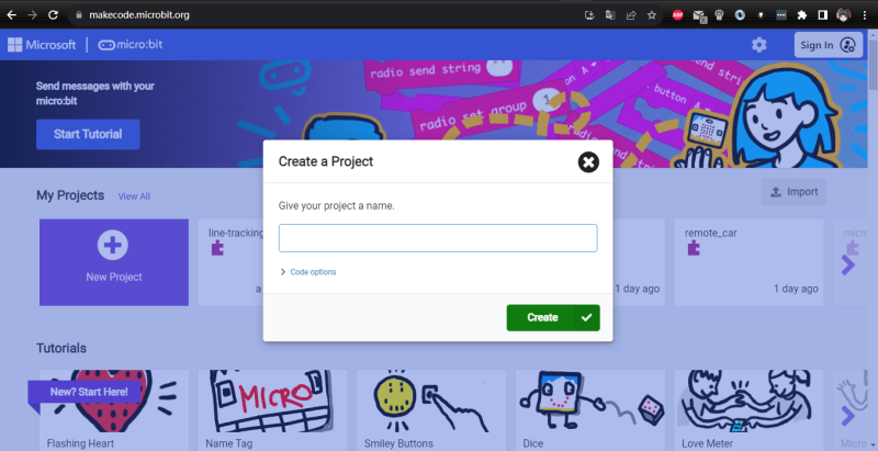
Create you project and input a name for it.
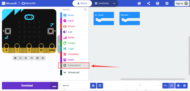
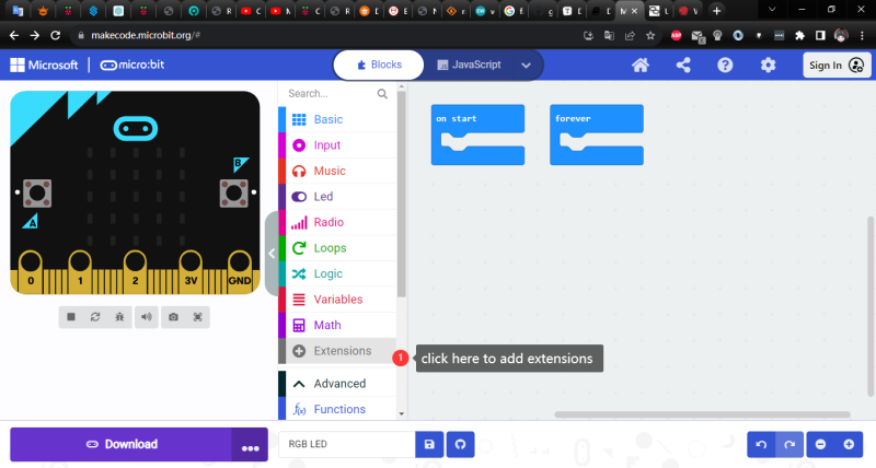
Click Extensions:
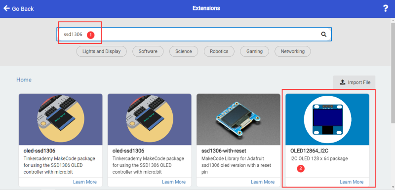
Input extension name and enter to search it.
For example, If you want to use OLED display, just input: ssd1306 and click search.
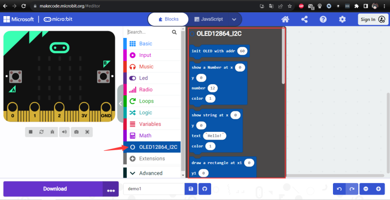
Make sure it has been added to your editor.
and then you can build your own project as well.
OLED Display Project
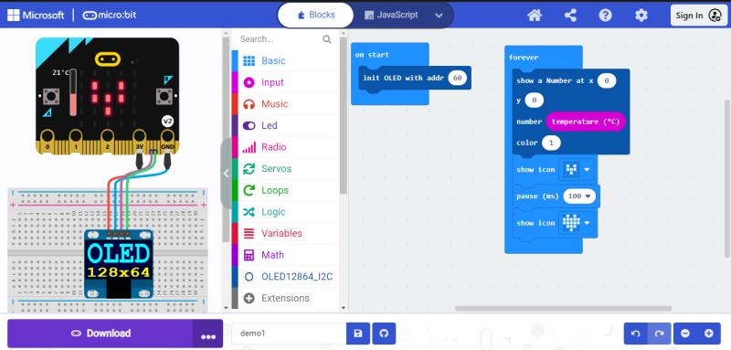
- 1. Build your own circuit, connect the SDA Pin on OLED to Micro:Bit extension board’s SDA Pin, connect the SCL Pin on OLED to Micro:Bit extension board’s SCL Pin, connect VCC pin to 3V3 Pin, connect the GND Pin to Micro:Bit extension board’s GND Pin. and then drag the block as following figure.
Upload code and you will see:
you can modify the number of x position and y position to move the position of the temperature number.
Servo Project
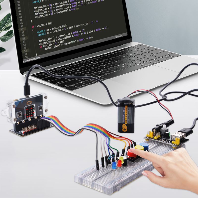
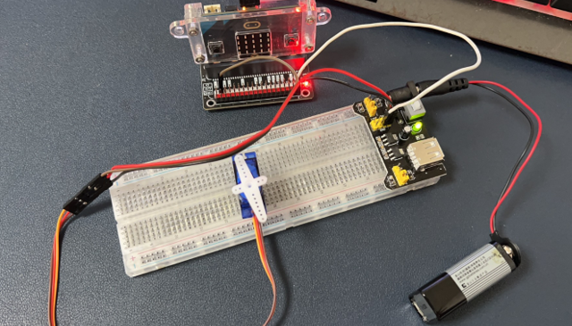
For example, if you want to use servo to build you own project, please use breadboard power supply module and breadboard to build the circuit, and power the servo by using 9V battery. you can build your own circuit like this:
Connect the servo to breadboard power supply module on 5V and GND pin. Red wire to 5V pin, brown wire to GND pin, orange pin connect to Micro:Bit extension board on Pin `P0`, and make sure it shares the same ground with power supply module, connect the GND Pin on breadboard power supply module to Micro:Bit extension board’s GND pin which is black pin.
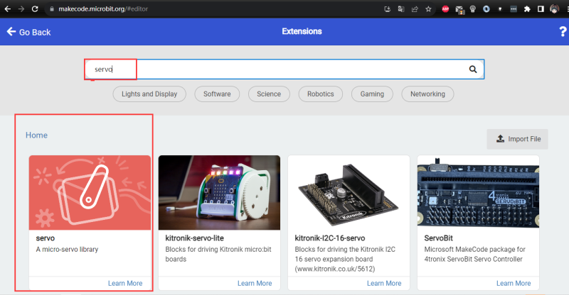
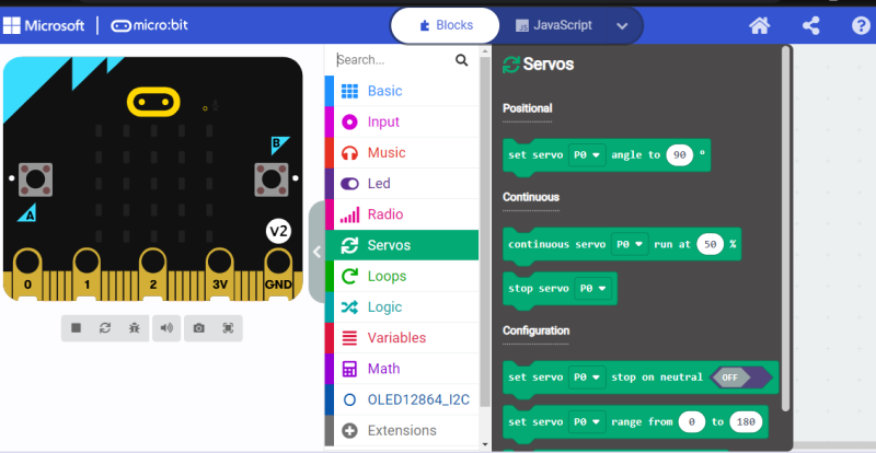
and open a browser, typing: [ https://makecode.microbit.org/ ] , create a new project called servo_test, and adding extensions
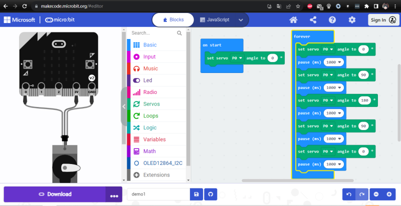
and then, click download button to download the. hex file to Micro:Bit, and press the power switch on breadboard power supply module, you will find the servo are spinning for 0 degree to 180 degree and into an infinity loop.
Heart Beating with buzzer:
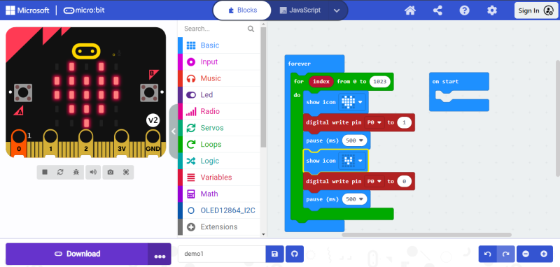
Connect the P0 to “+” pin of the buzzer and connect the short Pin(GND) to GND Pin on Micro:Bit’s GND pin, and make sure the block diagram as following figure, download the .hex file to Micro:Bit, you will hear the buzzer ringing and heart beating.
RGB Light Strip Project
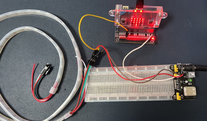
- Build circuit.
- Connect the 5V pin of RGB light strip to 5V pin on Breadboard power supply module.
- Connect the GND Pin of RGB light strip to GND pin on breadboard power supply module.
- Connect the DIN Pin of RGB light strip to P1 Pin (or other pin which has silk mark: AIN) on Micro:Bit extension board.
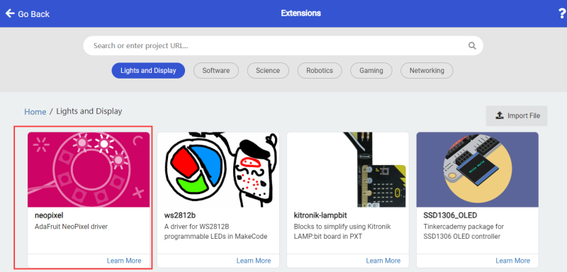
and then open browser and open Makecode URL and then adding ws2812 extensions as following steps:
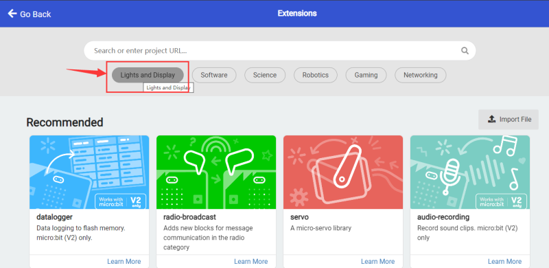
and then click Lights and Display:
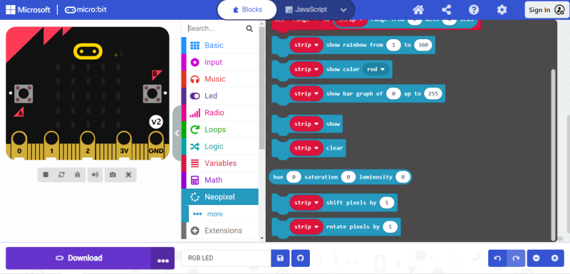
select neopixel
check if the extensions has been installed properly.
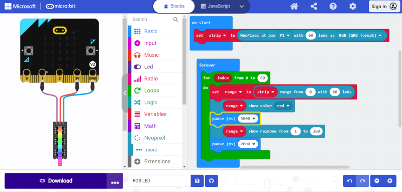
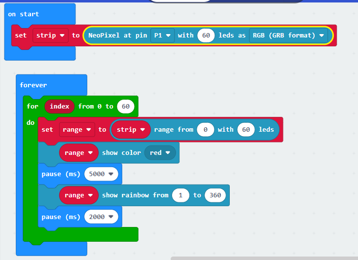
Next step is to drag block to build your own project, for example.
Click download button and after downloading, you will see following figure.
- More demo please visit: [ https://github.com/geeekpi/microbit_democodes ]
NOTE:
If you have any trouble with this kit, please kindly let us know by emailing to: support@52pi.com we will provide the best service to you! have a nice day and have fun!
Package Includes
- 1 x MicroBit basic starter kit
Keywords
- MicroBit basic starter kit, starter kit, microbit, basic starter kit, kit, microbit v2 kit, microbit kit.
