X205 SKU: EZ-0046: Difference between revisions
No edit summary |
No edit summary |
||
| Line 48: | Line 48: | ||
[[File:X205test1.jpg|left]] | [[File:X205test1.jpg|left]] | ||
<br style="clear:both;"> | <br style="clear:both;"> | ||
---- | |||
==PACKING LIST== | |||
*1 x X205 expansion board | |||
*1 x USB adapter | |||
*1 x 2.4GHz WIFI antenna | |||
*4 x nylon spacers (M3 x 20mm) | |||
*8 x nylon screws (M3 x 6mm) | |||
---- | |||
==QUICK START GUIDE == | |||
*A. Fitting the expansion board | |||
*B. Operation system | |||
*C. Power supply | |||
*D. RS232 communications | |||
*E. Testing of RS485 communications | |||
*F. Microphone input and audio output | |||
*G. Audio input and output interface | |||
*H. Setting RTC time | |||
*I. Setting up the IR remote | |||
*J. ULN2803 8-channel RC servo port | |||
---- | |||
**A. FITTING THE EXPANSION BOARD<br> | |||
1. Push a screws up through the mounting hole on the underside of the Raspberry Pi and screw the spacer down until it is hand tight<br> | |||
[[File:Assembly 275p1.jpg|left]] | |||
<br style="clear:both;"> | |||
----- | |||
2. Plugs the expansion board straight into your Raspberry Pi B+'s GPIO header and screw down.<br> | |||
[[File:Assembly 275p2.jpg|left]] | |||
<br style="clear:both;"> | |||
---- | |||
3. Insert the USB adapter | |||
[[File:Assembly 275p4.jpg|left]] | |||
<br style="clear:both;"> | |||
---- | |||
4. Install the WiFi antenna | |||
[[File:Assembly 275p5.jpg|left]] | |||
<br style="clear:both;"> | |||
---- | |||
==B. OPERATION SYSTEM== | |||
[[File:Rpi.jpg|left]] | |||
<br style="clear:both;"> | |||
[https://www.raspberrypi.org/downloads/raspbian/ Download] | |||
---- | |||
==C. POWER SUPPLY== | |||
Xseries expansion board supplies the RPi with a regulated +5V through the GPIO header using a 2A poly-resettable (PTC) fuse.<br> | |||
With the wide voltage input range (6~21Vdc), the RPi can be powered from a wide variety of external sources such as batteries, 12V power adapters, solar battery sources, etc. <br> | |||
<br> | |||
Recommended Power Adapter : 110~240VAC input, 12VDC 2A output <br> | |||
Dimension of input plug (Unit: mm)<br> | |||
[[File:Ds0101.jpg]] | |||
<br style="clear:both;"> | |||
---- | |||
D. RS232 COMMUNICATIONS | |||
Introduction | |||
The RS232 port is connected to the UART port on the Raspberry Pi using a MAX3232 interface. The MAX3232 IC converts the 3.3V UART port to RS232 voltages allowing communication with RS232 compatible devices over a DB9 serial cable or with the use of a null-modem cable the board allows terminal access with linux on the Raspberry Pi using a terminal application. The RS232 port can be accessed through the terminal block on x205. | |||
Schematic diagram | |||
---- | |||
==E. TESTING OF RS485 COMMUNICATIONS== | |||
---- | |||
==F. MICROPHONE INPUT AND AUDIO OUTPUT== | |||
---- | |||
==G. AUDIO INPUT AND OUTPUT INTERFACE== | |||
---- | |||
==H. SETTING RTC TIME== | |||
---- | |||
==I. TESTING THE IR RECEIVER== | |||
---- | |||
==J. ULN2803 8-CHANNEL RC SERVO PORT== | |||
---- | ---- | ||
Revision as of 17:29, 11 October 2016
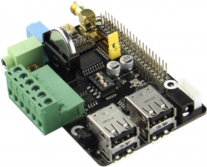
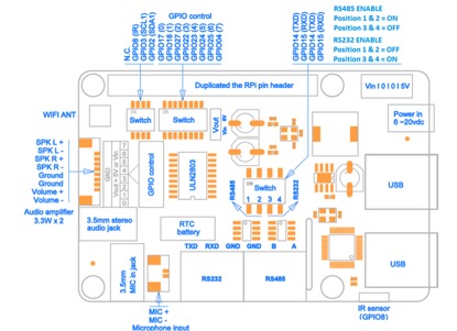
X205 EXPANSION BOARD FOR RASPBERRY PI
KEY FEATURES
| Parameters | Values |
|---|---|
| Input Voltage | 6V to 20Vdc converted to 5V, 3A via step-down DC/DC converter to power the Raspberry Pi |
| RS232 serial communications | Control the Raspberry Pi over RS232 or connect to external serial accessories |
| RS485 serial communications | You will be able to have a communication port for your field bus directly connected to your RPi!
- It will allow up to 32 devices to communicate through the same data line over a cable length of up to 4,000ft with a maximum data rate of 10Mbit/s. |
| Audio | 3.5mm MIC in jack
- 3.5mm stereo audio jack - Audio IO connector (Microphone input and stereo audio amplifier 3.3Wx2) |
| Wireless | WiFi (IEEE 802.11b/g/n) with external antenna
- IR sensor (38KHz) |
| USB Storage | Self-powered USB hub with 3 ports |
| Real-time clock (RTC) | Based on DS3231SN with included CR2032 battery |
| GPIO Control | 8-channel Darlington driver chip (ULN2803) allowing to control electronic circuits which require more current |
| Misc | Power output socket
- Camera flex slot so camera can still be used with the expansion board attached - DIP switch to remove connection from RPi’s pin header - Directly connected on top of the Raspberry Pi using the board GPIO header pins - No wiring nor soldering is required - Duplicated the 40-pin header of the R-Pi in order to support existing expansion boards - Suitable for Raspberry Pi Model B+, Raspberry pi 2 Model B and Raspberry Pi 3 Model B NEW! |
| Dimensions | 85 x 56mm (Same size as Raspberry Pi) |
PACKING LIST
- 1 x X205 expansion board
- 1 x USB adapter
- 1 x 2.4GHz WIFI antenna
- 4 x nylon spacers (M3 x 20mm)
- 8 x nylon screws (M3 x 6mm)
QUICK START GUIDE
- A. Fitting the expansion board
- B. Operation system
- C. Power supply
- D. RS232 communications
- E. Testing of RS485 communications
- F. Microphone input and audio output
- G. Audio input and output interface
- H. Setting RTC time
- I. Setting up the IR remote
- J. ULN2803 8-channel RC servo port
- A. FITTING THE EXPANSION BOARD
- A. FITTING THE EXPANSION BOARD
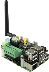
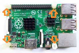
1. Push a screws up through the mounting hole on the underside of the Raspberry Pi and screw the spacer down until it is hand tight
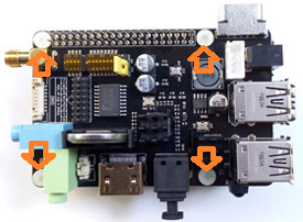
2. Plugs the expansion board straight into your Raspberry Pi B+'s GPIO header and screw down.
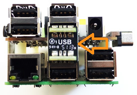
3. Insert the USB adapter
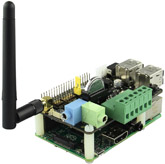
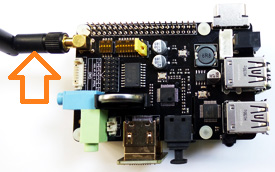
4. Install the WiFi antenna
B. OPERATION SYSTEM
C. POWER SUPPLY
Xseries expansion board supplies the RPi with a regulated +5V through the GPIO header using a 2A poly-resettable (PTC) fuse.
With the wide voltage input range (6~21Vdc), the RPi can be powered from a wide variety of external sources such as batteries, 12V power adapters, solar battery sources, etc.
Recommended Power Adapter : 110~240VAC input, 12VDC 2A output
Dimension of input plug (Unit: mm)

D. RS232 COMMUNICATIONS
Introduction
The RS232 port is connected to the UART port on the Raspberry Pi using a MAX3232 interface. The MAX3232 IC converts the 3.3V UART port to RS232 voltages allowing communication with RS232 compatible devices over a DB9 serial cable or with the use of a null-modem cable the board allows terminal access with linux on the Raspberry Pi using a terminal application. The RS232 port can be accessed through the terminal block on x205. Schematic diagram
