EP-0136: Difference between revisions
| (5 intermediate revisions by the same user not shown) | |||
| Line 110: | Line 110: | ||
===PCB Drawing=== | ===PCB Drawing=== | ||
===Function Area Display=== | ===Function Area Display=== | ||
===LED light status definition=== | |||
* Discharge Status | |||
{| class="wikitable" | |||
!Power C(%) !! LED1 !! LED2 !! LED3 !! LED4 | |||
|- | |||
| C >= 75% || ON || ON || ON || ON | |||
|- | |||
| 50% <= C <75% || ON || ON || ON || OFF | |||
|- | |||
| 25% <= C <50% || ON || ON || OFF || OFF | |||
|- | |||
| 3% <= C < 25% || ON || OFF || OFF || OFF | |||
|- | |||
| 0% <= C < 3% || 1.5Hz Blink || OFF || OFF || OFF | |||
|} | |||
<br style="clear:both;"> | |||
* Charging Status | |||
{| class="wikitable" | |||
!Power C(%) !! LED1 !! LED2 !! LED3 !! LED4 | |||
|- | |||
| 100% || ON || ON || ON || ON | |||
|- | |||
| 75% <= C|| ON || ON || ON || 1.5Hz Blink | |||
|- | |||
| 50% <= C <75% || ON || ON || 1.5Hz Blink || OFF | |||
|- | |||
| 25% <= C < 50% || ON || 1.5Hz Blink || OFF || OFF | |||
|- | |||
| C < 25% || 1.5Hz Shining || OFF || OFF || OFF | |||
|} | |||
==How To Assemble== | ==How To Assemble== | ||
| Line 135: | Line 166: | ||
<pre>The function of the switch button will no longer be available at this time.</pre> | <pre>The function of the switch button will no longer be available at this time.</pre> | ||
The Raspberry Pi will be running and please execute the following python script in the system terminal to complete the upgrade. | The Raspberry Pi will be running and please execute the following python script in the system terminal to complete the upgrade. | ||
* | * Download python scripts from github: | ||
<pre> | <pre> | ||
cd ~ | |||
git clone https://github.com/geeekpi/upsplus.git | |||
cd ~/upsplus | |||
python3 OTA_firmware_upgrade.py | |||
</pre> | |||
<font color=red><b>The first time it runs, it may prompt that the device is not registered.If it is a legal device, just wait a few seconds and try again.</b></font> | <font color=red><b>The first time it runs, it may prompt that the device is not registered.If it is a legal device, just wait a few seconds and try again.</b></font> | ||
* UPS Pro Will be turned off after upgrading, Please unplug the power supply, remove the batteries from UPS Pro. | * UPS Pro Will be turned off after upgrading, Please unplug the power supply, remove the batteries from UPS Pro. | ||
| Line 215: | Line 193: | ||
Please rest assured that every UPS we sell will Have a unique serial number so that we can provide battery quality analysis and feedback.<br> | Please rest assured that every UPS we sell will Have a unique serial number so that we can provide battery quality analysis and feedback.<br> | ||
It submits your UPS Pro operating status information to the server provided by us through a python script.<br> | It submits your UPS Pro operating status information to the server provided by us through a python script.<br> | ||
* Download Repository and execute: | |||
<pre> | <pre> | ||
cd ~ | |||
curl -Lso- https://git.io/JLygb | |||
</pre> | |||
When encountering low battery, it will automatically shut down and turn off the UPS and it will restart when AC power comes. | |||
===How To Setup RTC=== | |||
====Using Overlays==== | |||
* Overlays are loaded using the "dtoverlay" config.txt setting. | |||
As an example,consider I2C Real Time Clock drivers. In the pre-DT world these would be loaded | |||
by writing a magic string comprising a device identifier and an I2C address to | |||
a special file in /sys/class/i2c-adapter, having first loaded the driver for | |||
the I2C interface and the RTC device - something like this: | |||
PS: sudo su means use root user to operate the system file, otherwise you may encount an error: "Permission denied"<br> | |||
<pre> | |||
sudo modprobe i2c-bcm2835 | |||
sudo modprobe rtc-ds1307 | |||
sudo su | |||
echo ds1307 0x68 > /sys/class/i2c-adapter/i2c-1/new_device | |||
</pre> | |||
With DT enabled, this becomes a line in config.txt:<br> | |||
Edit /boot/config.txt file via vim.tiny tool or nano in a terminal: | |||
<code> sudo vim.tiny /boot/config.txt</code></br> | |||
And then add this parameter:<br> | |||
<pre> | |||
dtoverlay=i2c-rtc,ds1307 | |||
</pre> | |||
This causes the file /boot/overlays/i2c-rtc.dtbo to be loaded and a "node" | |||
describing the DS1307 I2C device to be added to the Device Tree for the Pi. By | |||
default it usees address 0x68, but this can be modified with an additional DT | |||
parameter: | |||
<pre> | |||
dtoverlay=i2c-rtc,ds1307,addr=0x68 | |||
</pre> | |||
Parameters usually have default values, although certain parameters are | |||
mandatory. See the list of overlays below for a description of the parameters | |||
and their defaults. | |||
===For Raspberry Pi 4B === | |||
Here we assume that you have already burned the Raspbian Image into TF card and connect to your PC and logged in. | |||
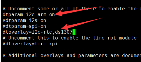
Open a terminal and modify /boot/config.txt file using what you favorate editor such as vim.tiny or nano, add parameters as following picture: | |||
[[File:DS1307-4B(1).png|thumb|left|500px]] | |||
<br style="clear:both;" > | |||
'''You can read /boot/overlay/README and find this info to add support for ds1307 I2C Real Time Clock device.''' | |||
[[File:DS1307-4B(2).png|thumb|left|500px]] | |||
<br style="clear:both;" > | |||
please ensure that /boot/config.txt file include two paramaters: | |||
<pre> | |||
dtoverlay=i2c-rtc,ds1307 | |||
dtparam=i2c_arm=on | |||
</pre> | |||
After that, please make sure you have disabled the "fake hwclock" which interferes with the 'real' hwclock<br> | |||
<pre> | |||
sudo apt-get -y remove fake-hwclock | |||
sudo update-rc.d -f fake-hwclock remove | |||
</pre> | |||
Now with the fake-hw clock off, you can start the original 'hardware clock' script.<br> | |||
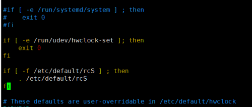
Edit the script file /lib/udev/hwclock-set with nano or vim editor and comment out these three lines:<br> | |||
<pre> | |||
if [ -e /run/systemd/system ] ; then | |||
exit 0 | |||
fi | |||
</pre> | |||
Finally result like this: <br> | |||
[[File:DS1307-4B(6).png|thumb|left|500px]] | |||
<br style="clear:both;"> | |||
save and reboot your RPi. | |||
---- | |||
===For Raspberry Pi 3B === | |||
Here we assume that you have already burned the Raspbian Image into TF card and connect to your PC and logged in. | |||
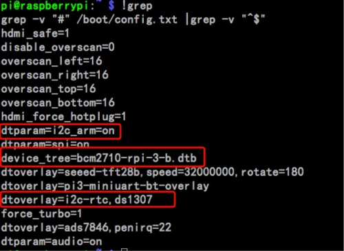
Open a terminal and modify /boot/config.txt file using what you favorate editor such as vim.tiny or nano, add parameters as following picture: | |||
[[File:Ds13076.png|thumb|left|500px]] | |||
<br style="clear:both;" > | |||
'''You can read /boot/overlay/README and find this info to add support for ds1307 I2C Real Time Clock device.''' | |||
<pre>Name: i2c-rtc | |||
Info: Adds support for a number of I2C Real Time Clock devices | |||
Load: dtoverlay=i2c-rtc,<param>=<val> | |||
Params: ds1307 Select the DS1307 device</pre> | |||
please ensure that /boot/config.txt file include those three paramaters: | |||
<pre> | |||
device_tree=bcm2710-rpi-3-b.dtb | |||
dtoverlay=i2c-rtc,ds1307 | |||
dtparam=i2c_arm=on | |||
</pre> | |||
After that, please make sure you have disabled the "fake hwclock" which interferes with the 'real' hwclock<br> | |||
</pre> | |||
<pre> | <pre> | ||
sudo apt-get -y remove fake-hwclock | |||
sudo update-rc.d -f fake-hwclock remove | |||
</pre> | </pre> | ||
Now with the fake-hw clock off, you can start the original 'hardware clock' script.<br> | |||
< | Edit the script file /lib/udev/hwclock-set with nano or vim editor and comment out these three lines:<br> | ||
<pre> | <pre> | ||
if [ -e /run/systemd/system ] ; then | |||
exit 0 | |||
fi | |||
</pre> | </pre> | ||
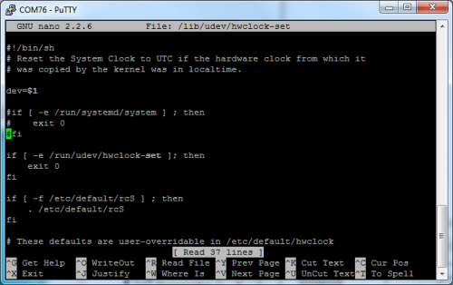
Finally result like this: <br> | |||
< | [[File:Raspberry pi hwclock-set.png|left|500px]] | ||
<br style="clear:both;"> | |||
save and reboot your RPi. | |||
===How To Estimate Battery Power=== | ===How To Estimate Battery Power=== | ||
Revision as of 17:31, 16 January 2021
UPS Plus
Descriptions
UPS Plus is a new generation of UPS power management module.
Features
- Easy to install
- Enhanced power management
- Remote OTA firmware upgrade
- Programmable BACK-TO-AC auto power up
- Programmable sample period
- I2C communication
- Standalone RTC
- Support stacked battery design
Specifications
- Current/voltage monitoring of Raspberry Pi power supply port.
- Battery terminal current/voltage monitoring, supports two-way monitoring of charge and discharge.
- Independent RTC function.
- OTA function (supports forced upgrade mode and active upgrade mode).
- Power estimation
Note: At least one full charge and discharge cycle must be completed!)
- Adjustable sampling period.
- Support FCP, AFC, SFCP fast charge protocol.
- Support BC1.2 charging protocol.
- Battery temperature monitoring
Note: the forced temperature protection cannot be turned off, threshold: 65 degrees!
- Programmable Power Voltage Detector(PVD) function, Default value: 3.6V
- Incoming call self-start function.
- Power down memory function.
- Programmable shutdown / forced restart.
- Running time statistics
- Electrostatic protection.
- Linear compensation range discharge capacity: 5V 4.5A.
- Non-linear compensation range discharge capacity: 5V 8A.
- Charging capacity 4.5V 5A/5V 2.5A/9V 2A/12V 1.5A.
- Stacked battery design
NOTE: Stacked power board need to be special accessories.Can not support None official accessories.
- Use I2C communication without occupying additional ports.
- Support 4.2V 4.35V 4.4V 4.5V lithium battery
Note: Different types of batteries cannot be mixed!
- After-sales data telemetry.
Register Mapping
USB Plus V5.0 Register Mapping Chart
- 0x17 - Operation Mode
| Address | Function | Range | Unit |
|---|---|---|---|
| 0x01 - 0x02 | Voltage of UPS's MCU | 2400 - 3600 | mV |
| 0x03 - 0x04 | Voltage of Pogopin's Bottom | 0 - 5500 | mV |
| 0x05 - 0x06 | Voltage of Batteries' Terminal | 0 - 4500 | mV |
| 0x07 - 0x08 | Voltage of USB-C Charging Port | 0 - 13500 | mV |
| 0x09 - 0x0A | Voltage of MicroUSB Charging Port | 0 - 13500 | mV |
| 0x0B - 0x0C | Batteries Temperature | -20 - 65 | ℃ |
| 0x0D - 0x0E | Full Voltage | 0 - 4500 | mV |
| 0x0F - 0x10 | Empty Voltage | 0 - 4500 | mV |
| 0x11 - 0x12 | Protection Voltage | 0 - 4500 | mV |
| 0x13 - 0x14 | Battery Remaining | 0 - 100 | % |
| 0x15 - 0x16 | Sample Period | 1 - 1440 | Min |
| 0x17 | Power Status/Operation Mode | 0/1 | Bool |
| 0x18 | Shutdown Countdown | 0/1 - 255 | Bool/Sec |
| 0x19 | Back-To-AC Auto Power up | 0/1 | Bool |
| 0x1A | Restart Countdown | 0/1 - 255 | Bool/Sec |
| 0x1B | Reset to Factory Defaults | 0/1 | Bool |
| 0x1C - 0x1F | Cumulative Running Time | 0 - 2147483647 | Sec |
| 0x20 - 0x23 | Accumulated Charging Time | 0 - 2147483647 | Sec |
| 0x24 - 0x27 | Running Time | 0 - 2147483647 | Sec |
| 0x28 - 0x29 | Version | 1 | Fixed |
| 0x2A - 0xEF | [Reserved] | NA | NA |
| 0xF0 - 0xFB | Serial Number | Device UID | Fixed |
| 0xFC - 0xFF | Factory Testing | NA | NA |
- 0x18 - OTA Firmware Upgrade Mode
| Address | Function |
|---|---|
| 0x01 - 0x10 | Encrypted buffer |
| 0x11 - 0xEF | [Reserved] |
| 0xF0 - 0xFB | Serial Number |
| 0xFC - 0xFF | Factory Test |
Gallery
PCB Drawing
Function Area Display
LED light status definition
- Discharge Status
| Power C(%) | LED1 | LED2 | LED3 | LED4 |
|---|---|---|---|---|
| C >= 75% | ON | ON | ON | ON |
| 50% <= C <75% | ON | ON | ON | OFF |
| 25% <= C <50% | ON | ON | OFF | OFF |
| 3% <= C < 25% | ON | OFF | OFF | OFF |
| 0% <= C < 3% | 1.5Hz Blink | OFF | OFF | OFF |
- Charging Status
| Power C(%) | LED1 | LED2 | LED3 | LED4 |
|---|---|---|---|---|
| 100% | ON | ON | ON | ON |
| 75% <= C | ON | ON | ON | 1.5Hz Blink |
| 50% <= C <75% | ON | ON | 1.5Hz Blink | OFF |
| 25% <= C < 50% | ON | 1.5Hz Blink | OFF | OFF |
| C < 25% | 1.5Hz Shining | OFF | OFF | OFF |
How To Assemble
How To Use
Automatic Shutdown Protection
- Download the latest Raspbian OS image from: [ https://www.raspberrypi.org/software/operating-systems/ ]
- Unzip it and flash it to MicroSD card(TF card) with Etcher imaging tool. [ https://www.balena.io/etcher/ ]
- Follow the installation method to assemble the Raspberry Pi and UPS Plus.
- After booting up and make sure Raspberry Pi can access internet.
- Open a terminal by press "Ctrl+ALT+T" or just click terminal icon on the task bar.
curl -Lso- https://git.io/JLygb
or
curl -Lso- https://raw.githubusercontent.com/geeekpi/upsplus/main/install.sh | bash
- When encountering low battery, it will automatically shut down and turn off the UPS and it will restart when AC power comes.
How To Update UPS Firmware via OTA
- Enter the OTA firmware upgrade mode:
Method 1
NOTE: Do not power off or disconnect the network during the upgrade process. If the upgrade fails, the UPS Pro will not work normally.
- Power off the Raspberry Pi.
- Cut off the external charging power (MicroUSB and USB-C)
- Take out all the batteries.
- Press and hold the UPS Pro switch key and insert the battery into the battery compartment.
At this time, the device will be forced to enter OTA mode.
The function of the switch button will no longer be available at this time.
The Raspberry Pi will be running and please execute the following python script in the system terminal to complete the upgrade.
- Download python scripts from github:
cd ~
git clone https://github.com/geeekpi/upsplus.git
cd ~/upsplus
python3 OTA_firmware_upgrade.py
The first time it runs, it may prompt that the device is not registered.If it is a legal device, just wait a few seconds and try again.
- UPS Pro Will be turned off after upgrading, Please unplug the power supply, remove the batteries from UPS Pro.
- Insert the batteries back to UPS Pro and then connect power supply and turn it on by press power switch.
Method 2
- Open a terminal and typing:
i2cset -y 1 0x17 50 127 b
- Shutdown Raspberry Pi and remove all batteries and power supply.
- Insert batteries back into the battery slot.
- Execute OTA.py python script.
- UPS Pro Will be turned off after upgrading, Please unplug the power supply, remove the batteries from UPS Pro.
- Insert the batteries back to UPS Pro and then connect power supply and turn it on by press power switch.
How To Enable Auto-Shutdown Protection Function
How To Collect Data
- Data Collection
Data collection will only collect information on abnormal voltage changes and battery charging and discharging status during equipment operation through UPS in order to provide better after-sales service, and will not collect your private information.
Please rest assured that every UPS we sell will Have a unique serial number so that we can provide battery quality analysis and feedback.
It submits your UPS Pro operating status information to the server provided by us through a python script.
- Download Repository and execute:
cd ~
curl -Lso- https://git.io/JLygb
When encountering low battery, it will automatically shut down and turn off the UPS and it will restart when AC power comes.
How To Setup RTC
Using Overlays
- Overlays are loaded using the "dtoverlay" config.txt setting.
As an example,consider I2C Real Time Clock drivers. In the pre-DT world these would be loaded
by writing a magic string comprising a device identifier and an I2C address to
a special file in /sys/class/i2c-adapter, having first loaded the driver for
the I2C interface and the RTC device - something like this:
PS: sudo su means use root user to operate the system file, otherwise you may encount an error: "Permission denied"
    sudo modprobe i2c-bcm2835
    sudo modprobe rtc-ds1307
    sudo su
    echo ds1307 0x68 > /sys/class/i2c-adapter/i2c-1/new_device
With DT enabled, this becomes a line in config.txt:
Edit /boot/config.txt file via vim.tiny tool or nano in a terminal:
sudo vim.tiny /boot/config.txt
And then add this parameter:
dtoverlay=i2c-rtc,ds1307
This causes the file /boot/overlays/i2c-rtc.dtbo to be loaded and a "node" describing the DS1307 I2C device to be added to the Device Tree for the Pi. By default it usees address 0x68, but this can be modified with an additional DT parameter:
dtoverlay=i2c-rtc,ds1307,addr=0x68
Parameters usually have default values, although certain parameters are mandatory. See the list of overlays below for a description of the parameters and their defaults.
For Raspberry Pi 4B
Here we assume that you have already burned the Raspbian Image into TF card and connect to your PC and logged in. Open a terminal and modify /boot/config.txt file using what you favorate editor such as vim.tiny or nano, add parameters as following picture:
You can read /boot/overlay/README and find this info to add support for ds1307 I2C Real Time Clock device.
please ensure that /boot/config.txt file include two paramaters:
dtoverlay=i2c-rtc,ds1307
dtparam=i2c_arm=on
After that, please make sure you have disabled the "fake hwclock" which interferes with the 'real' hwclock
sudo apt-get -y remove fake-hwclock
sudo update-rc.d -f fake-hwclock remove
Now with the fake-hw clock off, you can start the original 'hardware clock' script.
Edit the script file /lib/udev/hwclock-set with nano or vim editor and comment out these three lines:
if [ -e /run/systemd/system ] ; then
 exit 0
fi
Finally result like this:
save and reboot your RPi.
For Raspberry Pi 3B
Here we assume that you have already burned the Raspbian Image into TF card and connect to your PC and logged in. Open a terminal and modify /boot/config.txt file using what you favorate editor such as vim.tiny or nano, add parameters as following picture:
You can read /boot/overlay/README and find this info to add support for ds1307 I2C Real Time Clock device.
Name:   i2c-rtc
Info:   Adds support for a number of I2C Real Time Clock devices
Load:   dtoverlay=i2c-rtc,<param>=<val>
Params: ds1307                  Select the DS1307 device
please ensure that /boot/config.txt file include those three paramaters:
device_tree=bcm2710-rpi-3-b.dtb
dtoverlay=i2c-rtc,ds1307
dtparam=i2c_arm=on
After that, please make sure you have disabled the "fake hwclock" which interferes with the 'real' hwclock
sudo apt-get -y remove fake-hwclock
sudo update-rc.d -f fake-hwclock remove
Now with the fake-hw clock off, you can start the original 'hardware clock' script.
Edit the script file /lib/udev/hwclock-set with nano or vim editor and comment out these three lines:
if [ -e /run/systemd/system ] ; then
 exit 0
fi
Finally result like this:
save and reboot your RPi.
How To Estimate Battery Power
How To Adjust The Sampling Period
How To Monitor Battery Temperature
How To Enable UPS function
How To Configure Programmable Shutdown/Force Restart
FAQ
- Q: Why does the battery light go off sometime and lights up in a while?
- A: This is because the power chip performs battery re-sampling, and the purpose is that the data of inferior batteries is inaccurate during the sampling process.
- Q: Why is the power cut off every once in a while?
- A: Please check the battery charging current, the data discharge direction or the charging direction. If the load is too large, the charging may not be enough, which will cause this problem.
- Q: What kind of wall charger should I use?
- A: If the load is normal, it is recommended to use an ordinary 5V@2A charging head. If you need to carry a slightly higher load, it is recommended to use a fast charging source. We support FCP, AFC, SFCP protocols Fast charging source.
- Q: Can I directly input 9V and 12V to the USB port?
- A: No, if you must do this, you must remove the DP, DM and other related detection pins, and ensure that the power supply is stable.
- Q: I heard howling, why is this?
- A: Because of the no-load protection mechanism, the howling will disappear after the load is installed.
Keywords
- UPS Plus, GeeekPi UPS V5, UPS for Raspberry Pi


