S-0018: Difference between revisions
| Line 24: | Line 24: | ||
* Pin Definitions: GND, VCC, SCL, SDA | * Pin Definitions: GND, VCC, SCL, SDA | ||
* Pins: 4 pins | * Pins: 4 pins | ||
* Voltage: 3V | * Voltage: 3.3V DC | ||
* Working Temperature: -30°~ 70° | * Working Temperature: -30°~ 70° | ||
* Drive Duty: 1/64 Duty | * Drive Duty: 1/64 Duty | ||
Revision as of 18:48, 5 December 2022
Double Color 0.96 Inch OLED Display
Descriptions
This OLED display module is small, only 0.96" diagonal, it is made of 128x64 individual yellow and blue OLED pixels, each one is turn on or off by the controller chip.
It works without backlight, that is, in a dark environment OLED display is higher compared to that of LCD display you will like the miniature for its crispness.
That is, except the VCC and GND, 2 wires would be needed when using 4-wires I2C mode. Embedded Driver IC: SSD1306. Communication: I2C/IIC Interface, only need two I/O ports.
It compatibles with R3 board and Mega, Raspberry Pi, 51 Series MCU, STM32 etc.
No backlight is required, and the display unit can be self-luminous. It has ultra-high contrast, bright and clear dots, and it is easy to read even small fonts.
There are no fonts embedded in the OLED controller, users can create fonts through font generation software.
Features
- Fully compatible with for Arduino, 51 series, MSP430 Series, STM32/2, CSR IC, etc.
- Ultra-low power comsumption: full screen lit 0.08W
- Super high brightness and contrast are adjustable
- With embedded driver/controller
- Interface type is IIC (I2C)
- Pin Definitions: GND, VCC, SCL, SDA
- Pins: 4 pins
- Voltage: 3.3V DC
- Working Temperature: -30°~ 70°
- Drive Duty: 1/64 Duty
- High resoluton: 128*64 pixels(approx)
- Driver IC: SSD1306
- Display : Yello/Blue
Basic Specifications
Mechanical Specifications
- 1) Outline Drawing: According to the annexed outline drawing
- 2) Number of Pixels: 128x64
- 3) Panel Size: 27.50x27.80x3.0 (mm)
- 4) Active Area: 21.744x10.864 (mm)
- 5) Pixel Pitch: 0.17x0.17 (mm)
- 6) Pixel Size: 0.154x0.154 (mm)
- 7) Weight: 6(g)
Development Documentation
- SSD1306 Datasheet: File:Drive-1306.pdf
Gallery
How to program it
Raspberry Pi
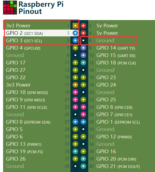
- Connect OLED display to Raspberry Pi GPIO as following Chart:
| OLED | Raspberry Pi GPIO |
|---|---|
| GND | GND |
| VCC | 3.3V |
| SCL | GPIO 3 (I2C1 SCL) |
| SDA | GPIO 2 (I2C1 SDA) |
- Full GPIO position
NOTE: We assume you are using the official operating system provided by the Raspberry Pi.
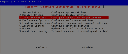
- Enable I2C function, open a terminal and typing:
sudo raspi-config
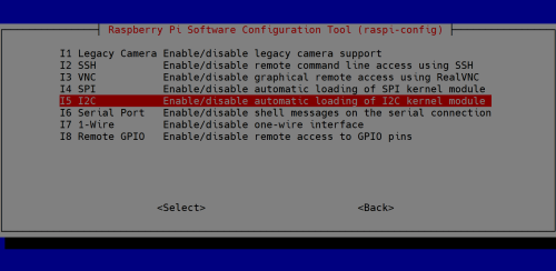
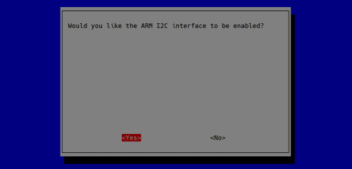
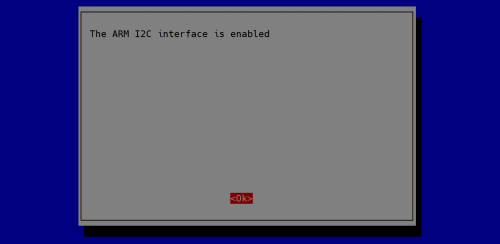
- Navigate to interface options and i2c item, enable it.
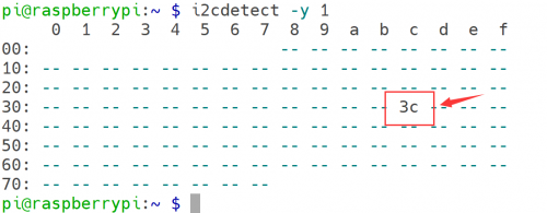
- Check if the OLED screen has been recognized.
i2cdetect -y 1
- Install dependencies libraries:
sudo apt -y install python3 python3-pip python3-pil libjpeg-dev zlib1g-dev libfreetype6-dev liblcms2-dev libopenjp2-7 libtiff5
- Grant privilleges to user `pi`
sudo usermod -a -G gpio,i2c pi
- Download sample code from this repo:
git clone https://github.com/rm-hull/luma.examples.git
cd luma.examples/
- Install the dependencies
sudo -H pip3 install -e .
- Entering into example folder and test it.
cd examples/
vim mydemo.py
- Paste following code.
#!/usr/bin/python3

import os
import sys
import time
from demo_opts import get_device
from luma.core.render import canvas
from PIL import ImageFont
import psutil
import subprocess as sp


def greetings():
    return "GeeekPi HI-Tech"

def get_temp():
    temp = sp.getoutput("vcgencmd measure_temp")
    return "CPU Temp:%s" % temp

def get_cpu_percent():
    cpu_percent = psutil.cpu_percent(interval=2)
    return "CPU Percent: %.1f" % (cpu_percent)

def get_cpu_count():
    cpu_count = psutil.cpu_count()
    return "CPU Count: %s" % (cpu_count)

def get_ip():
    ip = sp.getoutput("hostname -I")
    return "IP: %s" % ip

def stats(device):
    # use system font
    font_path = '/usr/share/fonts/truetype/dejavu/DejaVuSansMono.ttf'
    font_size = ImageFont.truetype(font_path, 13)

    with canvas(device) as draw:
        draw.text((0, 0), greetings(), font=font_size, fill="white")
        if device.height >= 32:
            draw.text((0, 15), get_cpu_percent(), font=font_size, fill="white")

        if device.height >= 64:
            draw.text((0, 30), get_temp(), font=font_size, fill="white")
            try:
                draw.text((0, 45), get_ip(), font=font_size, fill="white")

            except KeyboardInterrupt:
                pass

device = get_device()

while True:
    stats(device)
    time.sleep(2)
- Save it and Execute it:
sudo python3 mydemo.py &
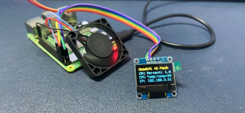
- You should seen this screen on OLED
Raspberry Pi Pico
MicroPython is a full implementation of the Python 3 programming language that runs directly on embedded hardware like Raspberry Pi Pico. You get an interactive prompt (the REPL) to execute commands immediately via USB Serial, and a built-in filesystem. The Pico port of MicroPython includes modules for accessing low-level chip-specific hardware.
- Download and Install Thonny IDLE: [[ https://thonny.org/ ]]
- Download and Install MicroPython Firmware: [[ https://www.raspberrypi.com/documentation/microcontrollers/micropython.html ]]
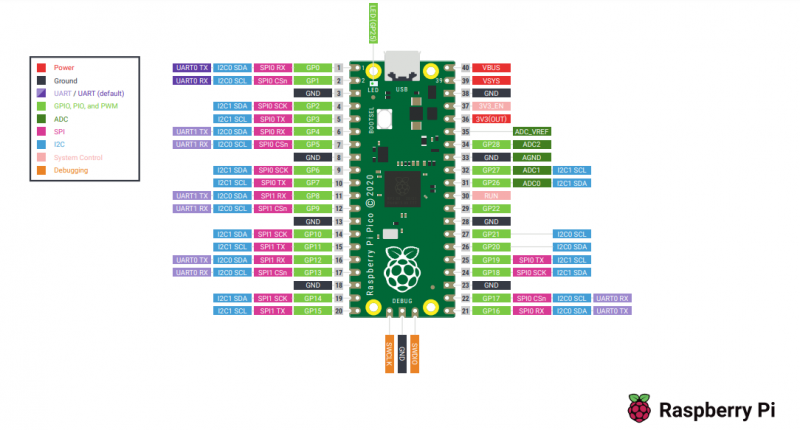
- Raspberry Pi Pico Pinout
- Build circuit
| Raspberry Pi Pico | OLED display |
|---|---|
| 3.3V(OUT) | VCC |
| GND | GND |
| GP0 | SDA |
| GP1 | SCL |
- Install ssd1306.py library.
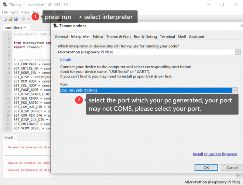
1. Connect Raspberry Pi Pico to PC via USB cable. 2. Open Thonny IDLE and select interpreter.
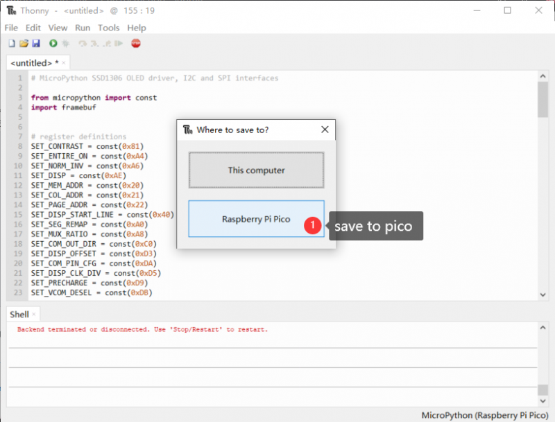
2. Open Thonny IDLE and create a new file, named ssd1306.py and paste following code:
# MicroPython SSD1306 OLED driver, I2C and SPI interfaces

from micropython import const
import framebuf


# register definitions
SET_CONTRAST = const(0x81)
SET_ENTIRE_ON = const(0xA4)
SET_NORM_INV = const(0xA6)
SET_DISP = const(0xAE)
SET_MEM_ADDR = const(0x20)
SET_COL_ADDR = const(0x21)
SET_PAGE_ADDR = const(0x22)
SET_DISP_START_LINE = const(0x40)
SET_SEG_REMAP = const(0xA0)
SET_MUX_RATIO = const(0xA8)
SET_COM_OUT_DIR = const(0xC0)
SET_DISP_OFFSET = const(0xD3)
SET_COM_PIN_CFG = const(0xDA)
SET_DISP_CLK_DIV = const(0xD5)
SET_PRECHARGE = const(0xD9)
SET_VCOM_DESEL = const(0xDB)
SET_CHARGE_PUMP = const(0x8D)


# Subclassing FrameBuffer provides support for graphics primitives
# http://docs.micropython.org/en/latest/pyboard/library/framebuf.html
class SSD1306(framebuf.FrameBuffer):
    def __init__(self, width, height, external_vcc):
        self.width = width
        self.height = height
        self.external_vcc = external_vcc
        self.pages = self.height // 8
        self.buffer = bytearray(self.pages * self.width)
        super().__init__(self.buffer, self.width, self.height, framebuf.MONO_VLSB)
        self.init_display()

    def init_display(self):
        for cmd in (
            SET_DISP | 0x00,  # off
            # address setting
            SET_MEM_ADDR,
            0x00,  # horizontal
            # resolution and layout
            SET_DISP_START_LINE | 0x00,
            SET_SEG_REMAP | 0x01,  # column addr 127 mapped to SEG0
            SET_MUX_RATIO,
            self.height - 1,
            SET_COM_OUT_DIR | 0x08,  # scan from COM[N] to COM0
            SET_DISP_OFFSET,
            0x00,
            SET_COM_PIN_CFG,
            0x02 if self.width > 2 * self.height else 0x12,
            # timing and driving scheme
            SET_DISP_CLK_DIV,
            0x80,
            SET_PRECHARGE,
            0x22 if self.external_vcc else 0xF1,
            SET_VCOM_DESEL,
            0x30,  # 0.83*Vcc
            # display
            SET_CONTRAST,
            0xFF,  # maximum
            SET_ENTIRE_ON,  # output follows RAM contents
            SET_NORM_INV,  # not inverted
            # charge pump
            SET_CHARGE_PUMP,
            0x10 if self.external_vcc else 0x14,
            SET_DISP | 0x01,
        ):  # on
            self.write_cmd(cmd)
        self.fill(0)
        self.show()

    def poweroff(self):
        self.write_cmd(SET_DISP | 0x00)

    def poweron(self):
        self.write_cmd(SET_DISP | 0x01)

    def contrast(self, contrast):
        self.write_cmd(SET_CONTRAST)
        self.write_cmd(contrast)

    def invert(self, invert):
        self.write_cmd(SET_NORM_INV | (invert & 1))

    def show(self):
        x0 = 0
        x1 = self.width - 1
        if self.width == 64:
            # displays with width of 64 pixels are shifted by 32
            x0 += 32
            x1 += 32
        self.write_cmd(SET_COL_ADDR)
        self.write_cmd(x0)
        self.write_cmd(x1)
        self.write_cmd(SET_PAGE_ADDR)
        self.write_cmd(0)
        self.write_cmd(self.pages - 1)
        self.write_data(self.buffer)


class SSD1306_I2C(SSD1306):
    def __init__(self, width, height, i2c, addr=0x3C, external_vcc=False):
        self.i2c = i2c
        self.addr = addr
        self.temp = bytearray(2)
        self.write_list = [b"\x40", None]  # Co=0, D/C#=1
        super().__init__(width, height, external_vcc)

    def write_cmd(self, cmd):
        self.temp[0] = 0x80  # Co=1, D/C#=0
        self.temp[1] = cmd
        self.i2c.writeto(self.addr, self.temp)

    def write_data(self, buf):
        self.write_list[1] = buf
        self.i2c.writevto(self.addr, self.write_list)


class SSD1306_SPI(SSD1306):
    def __init__(self, width, height, spi, dc, res, cs, external_vcc=False):
        self.rate = 10 * 1024 * 1024
        dc.init(dc.OUT, value=0)
        res.init(res.OUT, value=0)
        cs.init(cs.OUT, value=1)
        self.spi = spi
        self.dc = dc
        self.res = res
        self.cs = cs
        import time

        self.res(1)
        time.sleep_ms(1)
        self.res(0)
        time.sleep_ms(10)
        self.res(1)
        super().__init__(width, height, external_vcc)

    def write_cmd(self, cmd):
        self.spi.init(baudrate=self.rate, polarity=0, phase=0)
        self.cs(1)
        self.dc(0)
        self.cs(0)
        self.spi.write(bytearray([cmd]))
        self.cs(1)

    def write_data(self, buf):
        self.spi.init(baudrate=self.rate, polarity=0, phase=0)
        self.cs(1)
        self.dc(1)
        self.cs(0)
        self.spi.write(buf)
        self.cs(1)
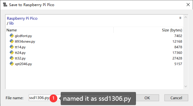
Save it to pico's lib folder( you can create by right click the blank area)
please make sure the library's name is ssd1306.py
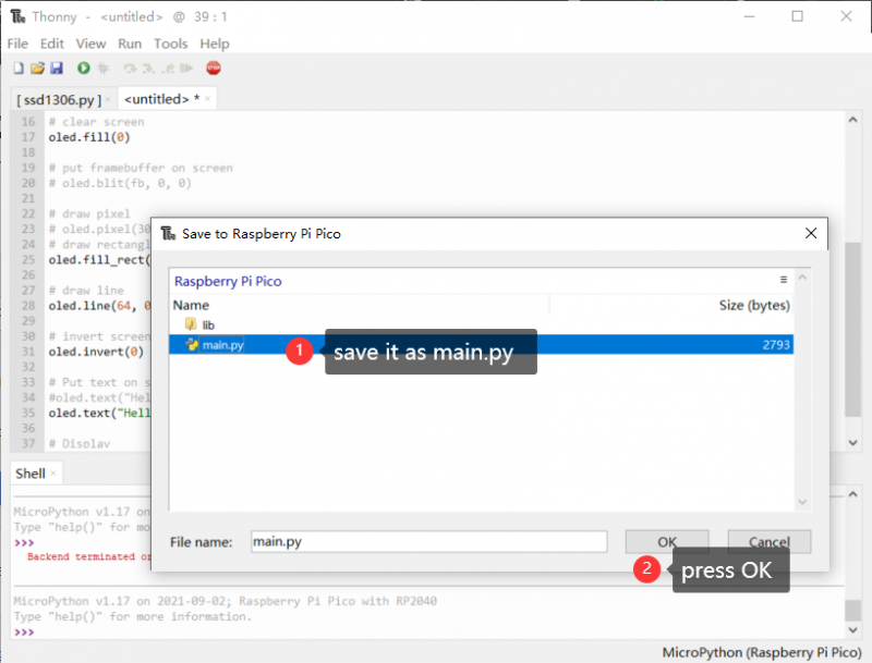
- Create a new file and named it main.py, and copy following code and paste it into it.
from machine import Pin, I2C, ADC
from ssd1306 import SSD1306_I2C
import framebuf
import time

WIDTH = 128
HEIGHT = 64


i2c = I2C(0, scl=Pin(1), sda=Pin(0),freq=200000)
print(i2c)

oled = SSD1306_I2C(WIDTH, HEIGHT, i2c)

# clear screen
oled.poweroff()
oled.poweron()

oled.fill(0)

# draw pixel
# oled.pixel(30, 33, 1)
# draw rectangle
for i in range(1, 100):
    oled.fill_rect(20, 25, 25, 25, 1)
    oled.fill_rect(70, 25, 25, 25, 1)
    oled.show()
    time.sleep(0.2)
    oled.fill(0)
    oled.fill_rect(25, 25, 25, 25, 1)
    oled.fill_rect(75, 25, 25, 25, 1)
    oled.show()
    time.sleep(0.2)
    oled.fill(0)

# draw line
#oled.line(35, 0, 64, 57, 1)

# invert screen 0/1
#oled.invert(0)

# Put text on screen
#oled.text("Hello World", 0, 0)
oled.text("Hello Pico", 0, 57)

# Display
oled.show()
Save it to main.py and click play button on Thonny IDLE.
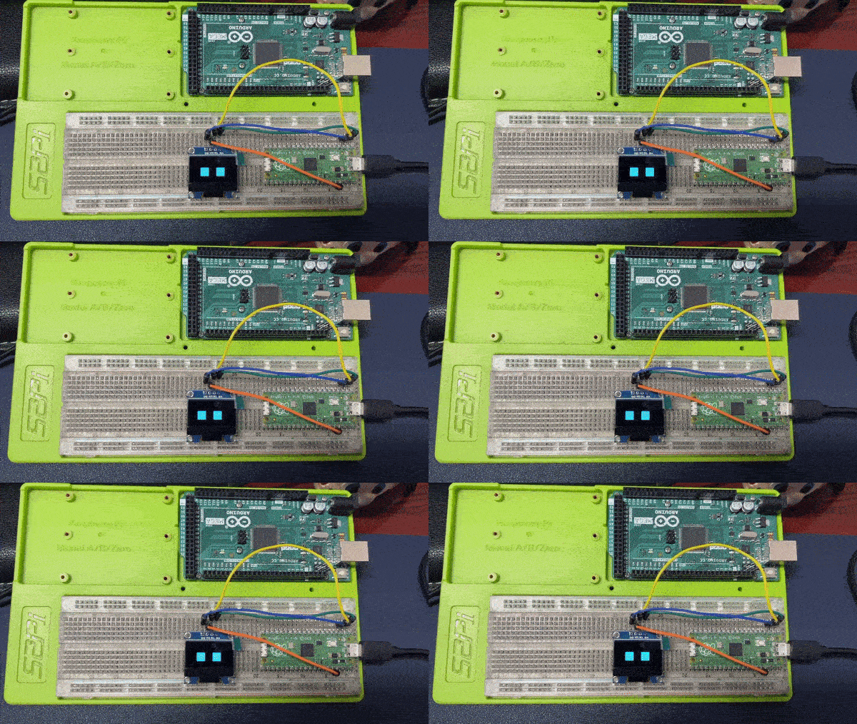
- OLED effect:
Arduino
- To program for Arduino, we need:
- Arduino IDE: [ https://www.arduino.cc/en/software ], Please download and install it.
Hardware Required:
- 1 x Arduino UNO or Arduino Mega 2560 or Arduino Other type.
- 1 x USB 2.0 Cable type A/B
- 1 x 0.96 inch OLED display
- 4 x Jumper wires (male to male)
- 1 x Breadboard
I2C 0.96 inch OLED display Pinout
- GND Pin: should be connected to the ground of Arduino.
- VCC Pin: is the power supply for the display which we connect the 5 volts or 3.3 volts pin on the Arduino.(Recommend connect to 3.3V)
- SCL Pin: serial clock pin for I2C interface.
- SDA Pin: serial data pin for I2C interface.
How to use OLED with Arduino
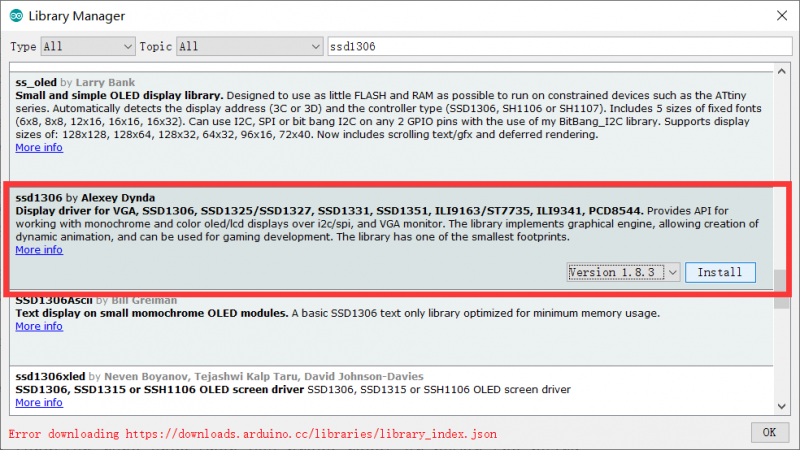
- On Arduino IDE, Go to Tools >> Manage Libraries and search SSD1306 or just download the latest zip file from [[ https://www.arduino.cc/reference/en/libraries/ssd1306/ ]], or just download from: File:Ssd1306-1.8.3.zip
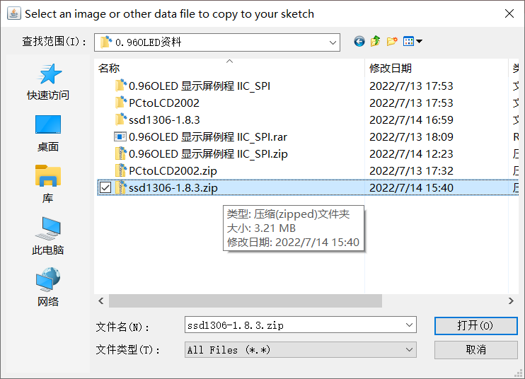
- If you download zip file from libraries URL, please install it before you use it.
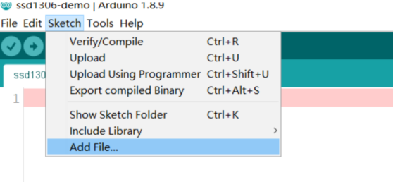
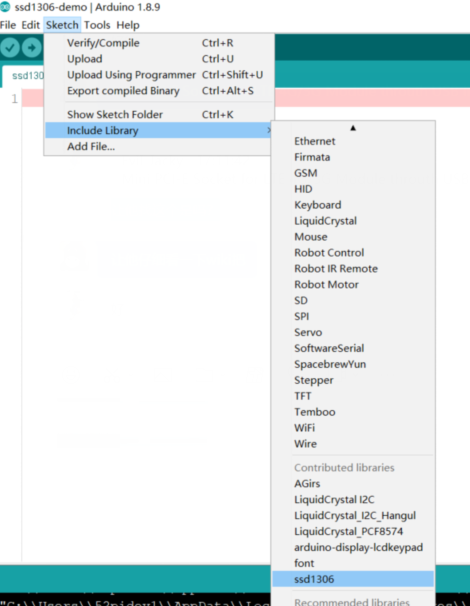
Install it as following steps:
when you coding, you can find it from sketch>> include libraries>> ssd1306
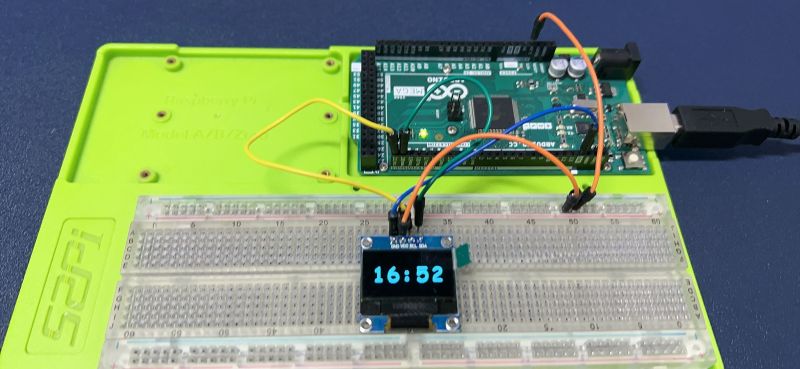
- Demo code: File:Clock.zip
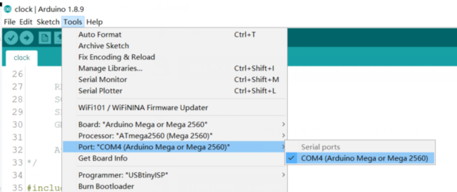
Download this demo code and unzip it to desktop, and connect your Arduino to your laptop or PC, select the serial port to upload code. For example:
Press CTRL+ R to verify or compile code, and press CTRL+U to upload code to your Arduino board.
STM32
- Project Package Download: File:0.96OLED STM32F103ZET6 IIC V1.0.zip
51 Series
- STC89C51 Series Demo Package: File:0.96OLED STC89C51 series I2C.zip
- Circuit connection diagram
| OLED Display | C51 Series MCU |
|---|---|
| GND | GND |
| VCC | 3.3V / 5V |
| D0(SCL) | P1^0 |
| D1(SDA) | P1^1 |
| RST(RES) | 3.3 |
| DC(DC) | GND |
| CS | GND |
Package Includes
- 1 x 0.96 inch OLED Display kit
Keywords
- 0.96 inch OLED display, double color 0.96 inch OLED display

