NightLight Hat Board For Raspberry Pi SKU: EP-0098
NightLight Hat Board For Raspberry Pi
Description
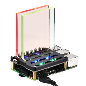
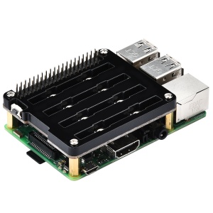
NightLight Hat Board For Raspberry Pi is a Hat Board which have 8 WS2812 RGB LED lights.
And this Hat Board will communicate with Raspberry Pi via I2C protocol.
You can control each LED's color individually by command.
At the same time, you can also adjust the brightness of each LED by command.
The light board is connected to the GPIO pin by HAT.
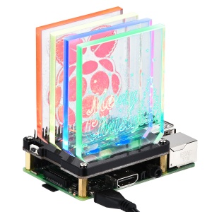
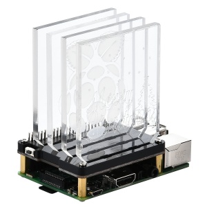
You can stack multiple identical boards in a layered manner, which can make your lighting more layered.
It is recommended not to exceed four layers at most. Otherwise, the power supply may be insufficient.
Because all the lights need to be powered from the GPIO pin of the Raspberry Pi.
The feature of the HAT board is that you don't have to worry about messy cables.
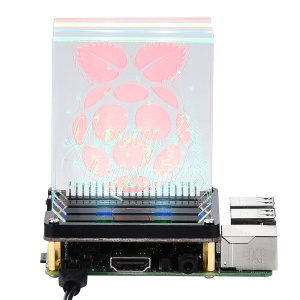
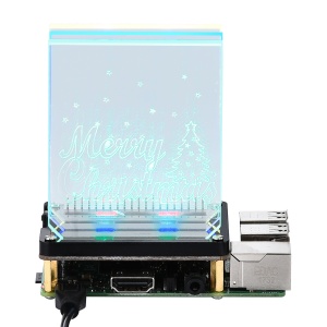
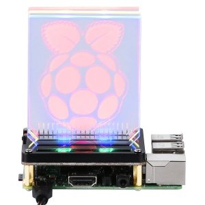
If you only use one layer of light board, you can engrave your favorite pattern on an acrylic board with a laser engraving machine,
and then insert it vertically into the random acrylic bracket,
so that by controlling the light, you can make different The acrylic art board presents a different brilliance, turning your light board into a work of art.
Features
- Easy to setup
- WS2812 RGB LEDs
- Extend the GPIO Pins
- Can be mounted on top of the stack
- Can Stack with other Stack board such as Relay module
- Individual control of each Light
- With beautiful acrylic light guide,Two factory-made patterns, two of them are blank for you DIY
- Plug and Play
- One command control
- Multiple Programming Language support such as shell, python, C/C++ and so on
Compatibility List
- Compatibility
| Platform | Nightlight Hat board | Notes |
|---|---|---|
| Raspberry Pi 3 Model A Plus | √ | |
| Raspberry Pi 3 Model B Plus | √ | |
| Raspberry Pi zero | √ | |
| Raspberry Pi zero W | √ | |
| Raspberry Pi 3 Model B | √ | |
| Raspberry Pi 2 Model B | √ | |
| Raspberry Pi Model B+ | √ |
Gallery
Package Includes
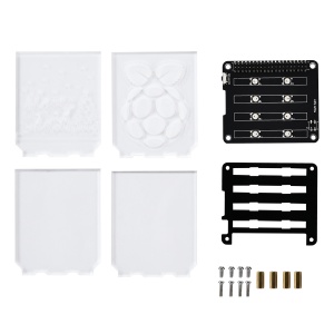
- 1 x NightLight Hat Board For Raspberry Pi
- 4 x M2.5x12 copper sticks
- 4 x M2.5x6 screws (Botton)
- 4 x M2.5x10 screws (Top)
- 1 x Acrylic Pattern Design (Stander)
- 4 x Acrylic Pattern Design (2x Caved and 2x blank)
How to use it
- Turn on the I2C interface
Open a terminal and Run sudo raspi-config
Use the down arrow to select 5 Interfacing Options.
Arrow down to P5 I2C .
Select yes when it asks you to enable I2C.
Also select yes if it asks about automatically loading the kernel module.
Use the right arrow to select the <Finish> button.
Select yes when it asks to reboot.
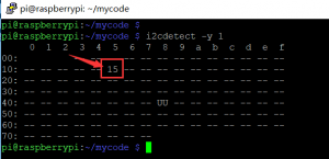
- Detect the register of the chip on board
i2cdetect -y 1
you will see this result:
- Lights up one LED
i2cset -y 1 0x15 0x01 0xff
 The first parameter "0x15" means the address of Nightlight hat.
"0x01" means the first LED's red color, every LED
has a register address, and you can follow this chart, "0xff" means give the LED 100% brightness
and "0x00" will turn of the LED, you can put the value from "0x00" to "0xff" to make a dim LED
Register Map
| Register Number | Color | Mark |
|---|---|---|
| 0x01 | red color | No.1 LED |
| 0x02 | green color | No.1 LED |
| 0x03 | blue color | No.1 LED |
| 0x04 | red color | No.2 LED |
| 0x05 | green color | No.2 LED |
| 0x06 | blue color | No.2 LED |
| 0x07 | red color | No.3 LED |
| 0x08 | green color | No.3 LED |
| 0x09 | blue color | No.3 LED |
| 0x0a | red color | No.4 LED |
| 0x0b | green color | No.4 LED |
| 0x0c | blue color | No.4 LED |
| 0x0d | red color | No.5 LED |
| 0x0e | green color | No.5 LED |
| 0x0f | blue color | No.5 LED |
| 0x10 | red color | No.6 LED |
| 0x11 | green color | No.6 LED |
| 0x12 | blue color | No.6 LED |
| 0x13 | red color | No.7 LED |
| 0x14 | green color | No.7 LED |
| 0x15 | blue color | No.7 LED |
| 0x16 | red color | No.8 LED |
| 0x17 | green color | No.8 LED |
| 0x18 | blue color | No.8 LED |
| 0x19 | button | 0x01 - Button Pressed 0x00 - Button Released |
Example Demo
- Shell script
simple script to light up all LED's individually in a loop.
#!/bin/bash
# lights up each LED individually in a loop.
#!/bin/bash
#

LED_array=(0x01 0x02 0x03 0x04 0x05 0x06 0x07 0x08 0x09 0x0a 0x0b 0x0c 0x0d 0x0e 0x0f 0x10 0x11 0x12 0x13 0x14 0x15 0x16 0x17 0x18)
while true
do
        for i in `seq 0 24`
        do
                i2cset -y 1 0x15 ${LED_array[i]} 0xFF   # turn on the led
                sleep 0.5                               # delay
                i2cset -y 1 0x15 ${LED_array[i]} 0x00   # turn of the led
                sleep 0.5                               # delay
        done
done
save this script in a file named "nightlight.sh" and then give it executive permission:
chmod +x nightlight.sh
sudo ./nightlight.sh
- Test DEMO in Language C
Please make sure your Raspberry Pi has been already connected to internet
In this demo, please make sure you have installed wiringPi library before you compile this C code.
sudo apt-get update
sudo apt-get -y install git-core
cd
git clone git://git.drogon.net/wiringPi
cd ~/wiringPi
git pull origin
cd ~/wiringPi
./build
- Test wiringPi’s installation
run the gpio command to check the installation:
gpio -v
gpio readall
That should give you some confidence that it’s working OK.
And then create a file called "nightlight.c" and write following code:
#include <stdio.h>
#include <wiringPi.h>
#include <wiringPiI2C.h>

#define BUTTON_REG_ADDR 0x19

int main(){
        int fd;
        int is_press = 1;
        int is_draw = 0;
        int i = 0;

        fd = wiringPiI2CSetup(0x15);

        for(i = 1;i<25;i++) wiringPiI2CWriteReg8(fd,i,0x00);

        for(;;)
        {
                if (wiringPiI2CReadReg8(fd, BUTTON_REG_ADDR) == 0x01 )
                {
                        is_press++;
                        is_draw = 1;
                        wiringPiI2CWriteReg8(fd,BUTTON_REG_ADDR, 0x0);
                }
                if(is_press && is_draw){
                        is_draw = 0;
                        for(i = 1;i<25;i++){
                                if(is_press > 3) is_press = 1;
                                if(((i + is_press) % 3) == 0)
                                {
                                        wiringPiI2CWriteReg8(fd,i,0xff);
                                }else{
                                        wiringPiI2CWriteReg8(fd,i,0x00);
                                }
                                delay(100);
                        }

                        wiringPiI2CWriteReg8(fd,BUTTON_REG_ADDR, 0x0);
                }
        }
}
save it and then compile it by this command:
gcc nightlight.c -lwiringPi -o nightlight
run it:
sudo ./nightlight
- Python script
you can also use Python script to driver the board.
first, make sure you have installed "smbus2" library.
if not, please open a terminal and input python and then:
sudo pip3 install smbus2
and then Create a new file named " nightlight.py" and copy and paste this code:
#!/usr/bin/env python
#
import time as t
import smbus

DEVICE_BUS = 1
DEVICE_ADDR = 0x15
bus = smbus.SMBus(DEVICE_BUS)

while True:
    try:
        for i in range(1,25):
            bus.write_byte_data(DEVICE_ADDR, i, 0xFF)
            t.sleep(0.2)
            bus.write_byte_data(DEVICE_ADDR, i, 0x00)
            t.sleep(0.2)
    except KeyboardInterrupt as e:
        print("Quit the Loop")
save it and run:
python nightlight.py
Keywords
- nightlight, dockerpi, raspberry pi, light, i2c, smbus2, iot
Video Tutorial
- Please follow the link:
- [ DockerPi NightLight Board Tutorial| https://youtu.be/KI7cQQLffG0 ]
