K-0291: Difference between revisions
Jump to navigation
Jump to search
| Line 14: | Line 14: | ||
* Easy to assemble | * Easy to assemble | ||
==How to assemble== | ==How to assemble== | ||
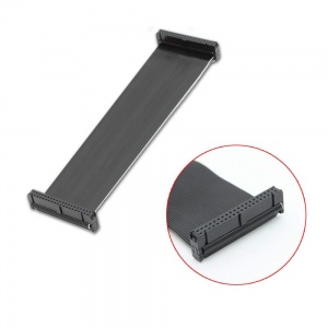
* 1. Connect the 40Pin wire to GPIO breakout board. | |||
** Please make sure the white wire connect to the pin holder, there is a trangle mark on the board. | |||
[[File:Gpiobreak006.jpg|left|300px]] | |||
<br style="clear:both;"> | |||
** Please make sure the white trangle against to the trangle mark which is on the 40 Pin wire. | |||
* 2. Connect the 40 Pin wire to your Raspberry Pi's GPIO, please make sure the white wire conncect to you Pi's GPIO Pin 1(3.3v) | |||
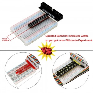
* 3. Connect the GPIO Breakout baord to the center of breadboard. | |||
[[File:Gpiobreak004.jpg|left|300px]] | |||
<br style="clear:both;"> | |||
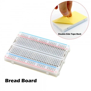
* 4. (Optional) Remove the protect film on breadboard and paste it to the project board. | |||
[[File:Gpiobreak003.jpg|left|300px]] | |||
<br style="clear:both;"> | |||
==Gallery== | ==Gallery== | ||
Revision as of 13:36, 22 August 2018
Raspberry Pi GPIO Breakout Board V1.1(T-Type)

Description
It is a breatout board for your Raspberry Pi's GPIO experiment.
It based on T type breakout board and made some changes, the board is fit for your breadboard perfectly.
And it compatiable for Raspberry Pi 2B/2B+/3B/3B+/Zero/ZeroW.
Features
- Smaller than before
- fit for GPIO experiment
- Clear GPIO function definitions shown
- BCM named GPIO lable
- Plug and Play
- Easy to assemble
How to assemble
- 1. Connect the 40Pin wire to GPIO breakout board.
- Please make sure the white wire connect to the pin holder, there is a trangle mark on the board.

- Please make sure the white trangle against to the trangle mark which is on the 40 Pin wire.
- 2. Connect the 40 Pin wire to your Raspberry Pi's GPIO, please make sure the white wire conncect to you Pi's GPIO Pin 1(3.3v)
- 3. Connect the GPIO Breakout baord to the center of breadboard.

- 4. (Optional) Remove the protect film on breadboard and paste it to the project board.

Gallery
 |
|
|