EP-0105: Difference between revisions
| Line 283: | Line 283: | ||
</pre> | </pre> | ||
===GPRS Connect with PPPd=== | ===GPRS Connect with PPPd(Raspberry Pi)=== | ||
A) First, replace the /boot/overlays/sc16is752-i2c.dtbo and make sure I2C is working properly. | A) First, replace the /boot/overlays/sc16is752-i2c.dtbo and make sure I2C is working properly. | ||
Revision as of 22:30, 2 July 2019
IoT Node(A)
Descriptions
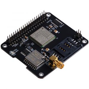
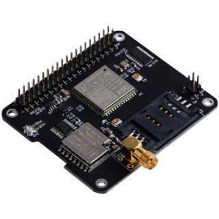
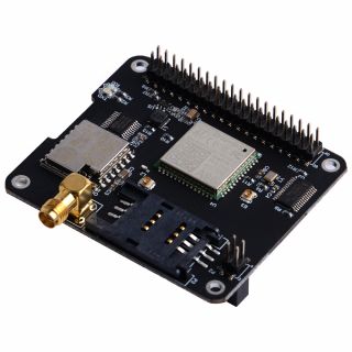
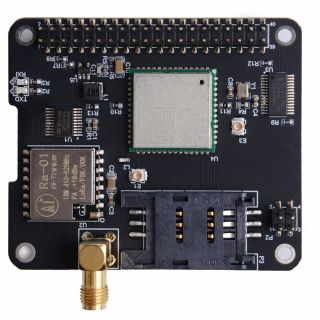
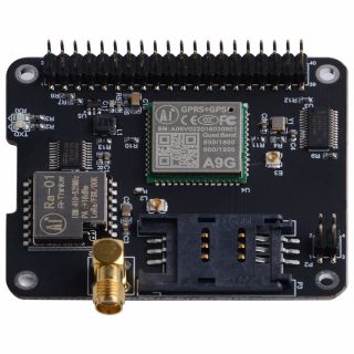
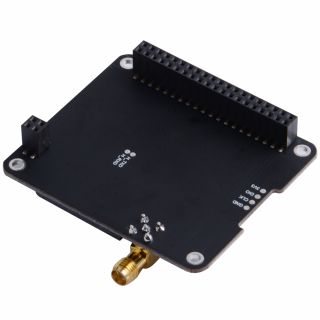
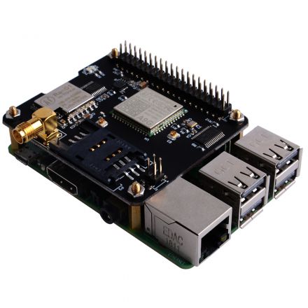
Iot Node(A) is one of Docker Pi series module.
It contains GSM module, GPS module and Lora module onboard.
Features
- Easy to Use
- Support I2C protocol communication
- High Quality A9G module
- High Quality Lora module
- Low Power Consumption
- Long Range Transmission
- Working temperature: 0°C ~ 65°C
- LORA antenna gain: 2db
- GPS antenna gain: 1.5db
- GSM antenna gain: 2db
- Supply voltage: 5V + 3V dual power supply
- Pure I2C communication, does not occupy other IO, leads to the GPIO pin.
Specifications
GPRS section
- 1. Low power consumption, standby sleep current <1mA
- 2. Support GSM/GPRS four frequency bands, including 850, 900, 1800, 1900MHZ;
- 3. GPRS Class 10;
- 4. Support GPRS data service, maximum data rate, download 85.6Kbps, upload 42.8Kbps;
- 5. Support standard GSM07.07, 07.05 AT commands, and access the serial port through I2C interface conversion.
- 6. AT commands support standard AT and TCP/IP command ports
GPS section
- 1. Support BDS/GPS joint positioning
- 2. Support A-GPS, A-BDS
- 3. Support standard SIM card
LORA section
- 1. City working conditions: transmission distance of 500 meters (RF parameters: 0x50)
In all cases: the minimum guaranteed 300 meters transmission.
- 2. Support FSK, GFSK, MSK, GMSK, LoRaTM and OOK modulation methods
- 3. Ultra-high receiver sensitivity as low as -141 dBm
- 4. Support preamble detection
- 5. Packet engine with CRC, up to 256 bytes
- 6. LORA transceiver indicator
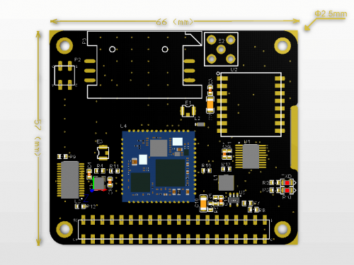
Mechanical Drawings
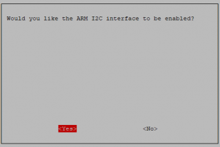
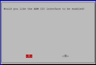
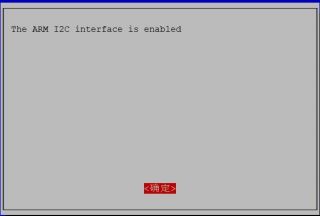
Configuring I2C(Raspberry Pi)
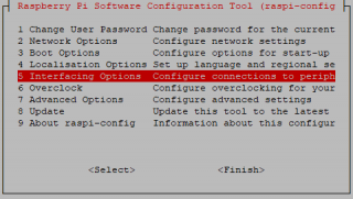
Run sudo raspi-config and follow the prompts to install i2c support for the ARM core and linux kernel
Go to Interfacing Options
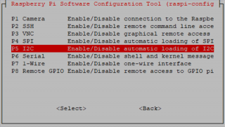
then I2C
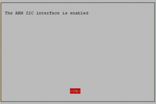
Enable!
Done!
Gallery
Documentations
- A9G Module Spicification: File:A9g product specification.pdf
- A9G Module AT Command Manual: File:A9G AT COMMAND manual.pdf
- A9G gprs series module at instruction set v1.0 File:A9G gprs series module at instruction set v1.0.pdf
- GPRS C SDK: File:GPRS C SDK-master.zip
Technical Details
A9G module
- Serial port : A9G module offers two serial port.
| Serial Port | Module name |
|---|---|
| /dev/ttySC0 | GPRS |
| /dev/ttySC1 | GPS |
Register Map
- Lora instruction section:
1) The 0x22 register is used to configure the parameters of the Lara.
After the register is written, it needs to write 1 at the corresponding position of the 0×23 register to make the setting take effect.
2) The first 16 bytes of the module are used to store the data specific address 0x01-0x10 that the user wants to send, and the 16 byte space from 0x11-0x21 is used to store the data received by the user.
| Register Address | 0x22 | |||||||
|---|---|---|---|---|---|---|---|---|
| Name | - | SpreadingFactor | SignalBandwidth | ErrorCoding | ||||
| Default Value | 0 | 1 | 0 | 1 | 1 | 0 | 1 | 1 |
| Description | Reserved | Band range 7-12 | Spread spectrum bandwidth 6-9 | Effective data ratio 1-4 | ||||
| Register Address | 0x23 | |||||||
|---|---|---|---|---|---|---|---|---|
| Default Value | 0 | 0 | 0 | 0 | 0 | 0 | 0 | 0 |
| Description | Write the setting parameters in the 0x22 address to Lora | Reset A9G module | Reserved | Reserved | Reserved | Reserved | Receive data set | Send user data |
| Register address | Function |
|---|---|
| 0x23 | register write reference |
| 0x01 | Send user data |
| 0x02 | Receive data set |
| 0x40 | Reset A9G |
| 0x80 | Set the Lora register |
How to use
How to assemble
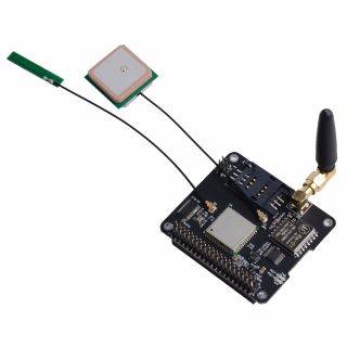
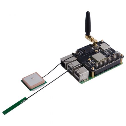
- Mount the Iot Node(A) board to Raspberry Pi
- Hookup GPS antana and Lora antana to IPX port.
- Screws the GPRS antana on the SMA port.
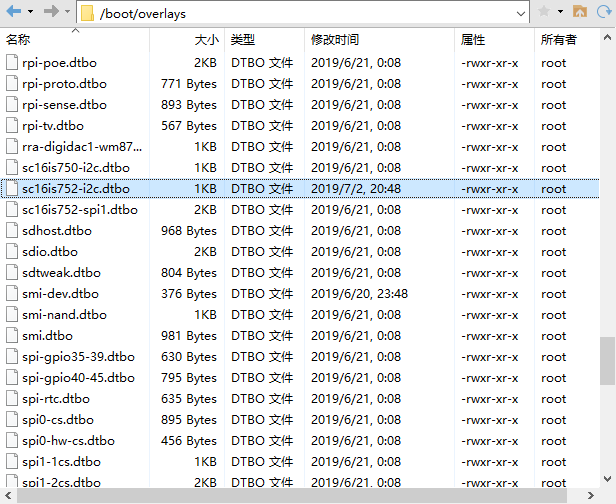
Replace /boot/overlays/sc16is752-i2c.dtbo(Raspberry Pi)
Replace /boot/overlays/sc16is752-i2c.dtbo file with this file: File:Sc16is752-i2c.zip
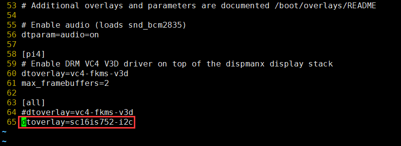
Modify /boot/config.txt file and add following parameter:
dtoverlay=sc16is752-i2c
How to configure
- FLash TF card with the latest raspbian image.
- Replace /boot/overlays/sc16is752-i2c.dtbo file with this file: File:Sc16is752-i2c.zip
NOTE: Please unzip it after donwloading.
- Modify /boot/config.txt file and add following parameter:
dtoverlay=sc16is752-i2c
- Turn on the I2C interface
Open a terminal and Run sudo raspi-config
Use the down arrow to select 5 Interfacing Options.
Arrow down to P5 I2C .
Select yes when it asks you to enable I2C.
Also select yes if it asks about automatically loading the kernel module.
Use the right arrow to select the <Finish> button.
- Open a terminal and typing:
sudo raspi-config
Navigate to interface options and then select i2c and enable it.
- Reboot Raspberry Pi
- Login Raspberry pi and make sure connect to internet, open a terminal and typing:
sudo apt-get update
sudo apt-get -y install gpsd gpsd-clients python-gps
- Modify "/etc/default/gpsd" file and add following parameters:
DEVICES="/dev/ttySC1"
GPSD_OPTIONS='-F /var/run/gpsd.sock'
How to use GPS module
- NOTE: GPS module is OUTDOOR module, please test it outside.
- Open a terminal and typing:
sudo systemctl restart gpsd.socket
sudo cgps -s
- Python Programming:
#!/usr/bin/env python3
import serial
import smbus
from gps import *
import os

# Restart gpsd service.
os.system("sudo systemctl restart gpsd.socket")
# Open serial port
ser = serial.Serial('/dev/ttySC0', 115200)

if ser.isOpen == False:
    ser.open()
try:
    print("Turn on GPS switch")
    ser.write(str.encode("AT+GPS=1\r"))
    time.sleep(1)
    os.system("sudo cgps -s")
except KeyboardInterrupt:
    ser.flushInput()
    ser.close()
- Save it and execute it:
chmod +x mygps.py
./mygps.py
How to use GPRS module
- Insert the SIM card(It may need you purchase from ISP vendor).
- Create a file named gprs.py
- Paste follow code into the file and save it.
#!/usr/bin/env python3
import serial
import time
import smbus
import operator
import os

print("Waiting for initializing...")
bus.write_byte_data(0x16,0x23,0x40)
time.sleep(2)

bus = smbus.SMBus(1)

ser = serial.Serial('/dev/ttySC0', 115200)

if ser.isOpen == False:
    ser.open()
try:
    print('-'*60)
    print("Initializing A9G GPRS module.")
    print("GSM connecting...")
    time.sleep(3)
    i = 0
    while True:
        ser.write(str.encode("AT+CCID\r"))
        size = ser.inWaiting()
        if size != 0:
            ticks = time.time()
            response = ser.read(size)
            ccid = str(response,encoding="utf-8")
            if(ccid.find("89860") != -1):
                ccid_result_tmp1 = ccid.splitlines()
                ccid_result = ccid_result_tmp1[2].split(": ")
                if len(ccid_result) > 1:
                    print("SIM card OK, Network access testing is normal. Please check whether the card serial number is the same. number:" + ccid_result[1]);
                    time.sleep(3)
                    print('-'*60)
            else:
                i = i + 1
                print("Waiting network, If the time is too long, it may be a malfunction, or the SIM card is bad.:" + str(i))
                ser.flushInput()
                time.sleep(1)
except KeyboardInterrupt:
    ser.close()
- Add executable rights and run:
chmod +x gprs.py
./gprs.py
GPRS Connect with PPPd(Raspberry Pi)
A) First, replace the /boot/overlays/sc16is752-i2c.dtbo and make sure I2C is working properly.
B)Enter command i2cset -y 1 0x16 0x23 0x40 to reset the GPRS module.
C)Enter command sudo apt install ppp to install ppp tools.
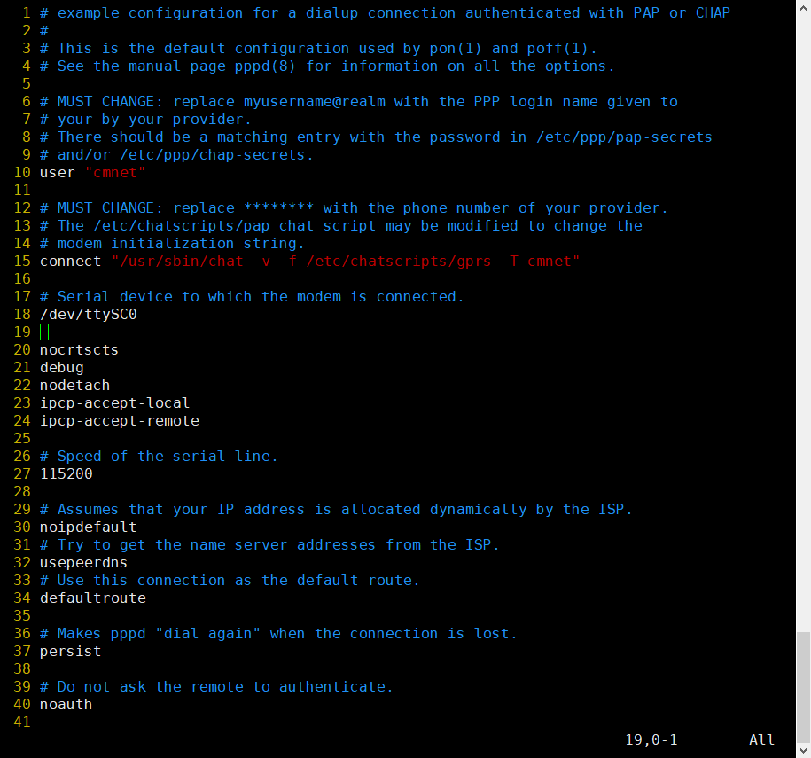
D)Copy /etc/ppp/peers/provider to /etc/ppp/peers/gprs E)Modify /etc/ppp/peers/gprs
- Line 10 : Please consult your service provider for the user (Example:cmnet).
- Line 15 : Please consult your service provider for the apn (Example:cmnet).
- Line 18 - Line 24:Recommended setting
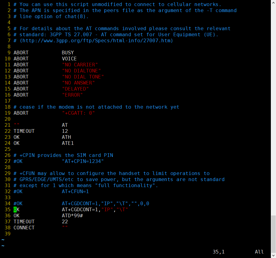
F)Modify /etc/chatscripts/gprs (Change Line 34 to Line 35)
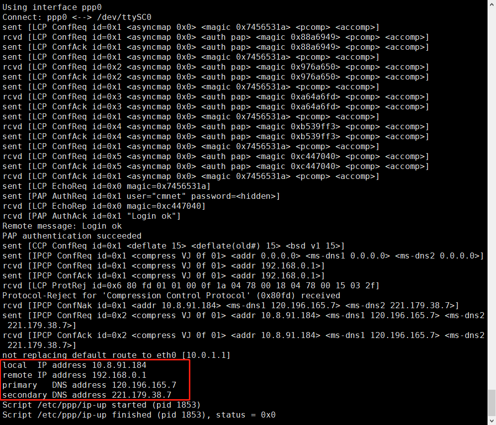
G)Enter command sudo pppd call gprs to dial up.
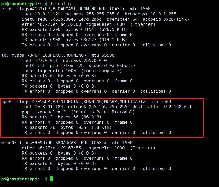
H)Check your ppp config from your ISP.
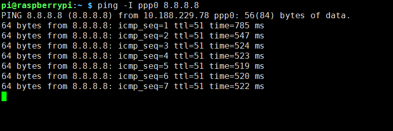
I)Enter command ping -I ppp0 8.8.8.8 test your network (If Internet available)
How to use Lora module
- Principle:
<pre. The transmitting device performs data transfermation role by transmitting data to each of the register addresses from 0x01 to 0x10. The receiving device acquires the transmitted data by reading data from each register of 0x11~0x21.
- Data sending example
Create a file named lora_sender.py and then copy and paste following code:
#!/usr/bin/env python3
import time
import smbus
import os
import sys

bus = smbus.SMBus(1)

try:
    print("Initialize LORA transmitter open")
    bus.write_byte_data(0x16,0x23,0x01)    # 0x01 means "send user data"
    # specify the data that you want to send.
    # for example, if you want to send 4 data to receiver, you put them in a list.
    # although you can input 10 set of data due to you have 10 register to use.
    data_list = [170,85,165,90]

    # define the register list that you want to use.
    register_list = [0x01,0x02,0x03,0x04]

    # write data to register and then the data will be send out.
    for index in range(0, len(data_list)):
        bus.write_byte_data(0x16,register_list[index],data_list[index])
        print("LORA send data to %d register %d data" %(register_list[index], data_list[index])
        time.sleep(1)
except KeyboardInterrupt:
    sys.exit()
finally:
    print("Quit the sending data program")
- Save it and run it:
chmod +x lora_sender.py
python3 lora_sender.py
- Receiving Data Example:
Create a file named "lora_receiver.py" and then copy and paste following code:
#!/usr/bin/env python3
import time
import smbus
import os
import sys

bus = smbus.SMBus(1)

try:
    print("Initialize LORA transmitter open")
    bus.write_byte_data(0x16,0x23,0x02)    # 0x02 means "read user data"
    # create a list to receive data from sender.
    resv_data = []

    # define the register list that you want to read from.
    register_list = [0x11,0x12,0x13,0x14]

    #Read each register's data and append to resv_data list.
    for index in range(0,len(register_list)):
        resv_data.append(bus.read_byte_data(0x16, register_list[index])

    print("Received data:")
    print(resv_data)
    time.sleep(1)
except KeyboardInterrupt:
    sys.exit()
finally:
    print("Quit the receiving data program.")
- Save it and run it:
chmod +x lora_receiver.py
python3 lora_receiver.py
How to build your own project with 4 channel Relay board
- Assemble Iot-Node(A) to Raspberry pi 3B/3B+/3A+/4B/Zero/Zero w.
- Assemble another Iot-Node(A) to another Raspberry pi 3B/3B+/3A+/4B/Zero/Zero w.
- Assemble 4 channel Relay board to one of them, and make sure you have already enabled i2c function on both of them.
- Download demo code from github:
git clone https://github.com/geeekpi/dockerpi.git
and follow the readme to run the demo code.
Package Include
- 1 x IoT Node(A) Board
- 4 x M2.5*11mm Copper stick
- 4 x M2.5 Nuts
- 1 x Instructions
FAQ
- Q: May i hotplug this module when it is running?
A: We sugguest that you turn off the raspberry pi and then plug the module.
Keywords
- IoT, lora, GPS, GPRS, GSM, antana, Raspberry pi 3B, Node, radio devices
