EP-0076: Difference between revisions
m (Yoyojacky moved page RPI-ADS1115-ADC-Module SKU:EP-0076 to EP-0076) |
|||
| (34 intermediate revisions by the same user not shown) | |||
| Line 1: | Line 1: | ||
=RPI-ADS1115-ADC-Module= | ==RPI-ADS1115-ADC-Module== | ||
[[File:Ads1115main.jpg|right|300px]] | |||
==Description== | |||
| | The ADS1115 are precision analog-to-digital converters (ADCs) with 16 bits of resolution offered in an ultra-small, an MSOP-10 package. <br> | ||
| | Data are transferred via an I2C-compatible serial interface, four I2C slave addresses can be selected, it operate from a single power supply at 3.3V.<br> | ||
| | It can be used to detect analog signal and convert it to digital signal.<br> | ||
You can attach a joy stick or other analog sensor such as NTC,temperature, dust sensor and so on.<br> | |||
==Compatibility List== | |||
* Compatibility | |||
{| class="wikitable" style="text-align: center;" | |||
|- | |||
!Platform !!ADS1115-ADC Module !! Notes | |||
|- | |||
|Raspberry Pi 3 Model B Plus|| √|| | |||
|- | |||
|Raspberry Pi zero ||√|| | |||
|- | |||
| Raspberry Pi zero W ||√|| | |||
|- | |||
|Raspberry Pi 3 Model B||√|| | |||
|- | |||
|Raspberry Pi 2 Model B||√|| | |||
|- | |||
|Raspberry Pi Model B+||×|| | |||
|- | |||
|} | |} | ||
==Features== | ==Features== | ||
| Line 30: | Line 31: | ||
! Parameters !! Values | ! Parameters !! Values | ||
|- | |- | ||
| | |Size: || 65.0mm x 30.0mm x 18.0mm | ||
|- | |- | ||
| | |Power Supply || 3.3v | ||
|- | |- | ||
| | |Analog Input Voltage || GND to VDD | ||
|- | |- | ||
|PROGRAMMABLE DATA RATE: || 8SPS to 860SPS | |PROGRAMMABLE DATA RATE: || 8SPS to 860SPS | ||
| Line 41: | Line 41: | ||
|INTERNAL LOW-DRIFT: ||VOLTAGE REFERENCE | |INTERNAL LOW-DRIFT: ||VOLTAGE REFERENCE | ||
|- | |- | ||
|INTERNAL | |INTERNAL PGA || Available | ||
|- | |- | ||
| | | Resolution || 16-bit | ||
|- | |- | ||
|I2C™ INTERFACE: || Pin-Selectable Addresses | |I2C™ INTERFACE: || Pin-Selectable Addresses | ||
|- | |- | ||
| | | Channels Number || 4 SINGLE-ENDED OR 2 DIFFERENTIAL INPUTS | ||
|- | |- | ||
|PROGRAMMABLE COMPARATOR || | |PROGRAMMABLE COMPARATOR || 2/3 ~ 16 | ||
|- | |||
| INTERNAL NTC Support || Available | |||
|} | |||
==Mechanical Drawing== | |||
[[File:Ads1115machinical.jpg|left|500px]] | |||
<br style="clear:both;"> | |||
==Schematic Diagram== | |||
[[File:AD transformation.jpg|left|500px]] | |||
<br style="clear:both;"> | |||
==Gallery== | |||
{| | |||
|[[File:Ads1115main.jpg|left|300px]] | |||
|[[File:Ads111503.jpg|none|300px]] | |||
|[[File:Ads111502.jpg|none|300px]] | |||
|[[File:Ads111504.jpg|none|300px]] | |||
|} | |} | ||
==How to wire up== | ==How to wire up== | ||
Just Plug into GPIO with this module. | Just Plug into GPIO with this module. | ||
| Line 57: | Line 71: | ||
[[File:Ads111501.jpg|left|500px]] | [[File:Ads111501.jpg|left|500px]] | ||
<br style="clear:both;"> | <br style="clear:both;"> | ||
==How to get analog data== | ==How to get analog data== | ||
* All steps are available that we've consumed that you have already flashed the newest image file into your TF card, and your RaspberryPi is powered on. | * All steps are available that we've consumed that you have already flashed the newest image file into your TF card, and your RaspberryPi is powered on. | ||
| Line 64: | Line 76: | ||
<code> sudo vim.tiny /boot/config.txt </code><br> | <code> sudo vim.tiny /boot/config.txt </code><br> | ||
<pre> | <pre> | ||
dtparam=i2c_arm=on | dtparam=i2c_arm=on | ||
</pre> | </pre> | ||
Save it and reboot your raspberry Pi. <br> | Save it and reboot your raspberry Pi. <br> | ||
| Line 80: | Line 90: | ||
*Alternatively you can install from pip with: | *Alternatively you can install from pip with: | ||
<code>sudo pip install adafruit-ads1x15</code><br> | <code>sudo pip install adafruit-ads1x15</code><br> | ||
* Change your work directory to Adafruit_Python_ADS1x15/example as following command:<br> | * Change your work directory to Adafruit_Python_ADS1x15/example as following command:<br> | ||
<code>cd ~/Adafruit_Python_ADS1x15/examples</code><br> | <code>cd ~/Adafruit_Python_ADS1x15/examples</code><br> | ||
<code>sudo python simpletest.py</code><br> | <code>sudo python simpletest.py</code><br> | ||
* You will see a chart like following picture:<br> | * You will see a chart like following picture:<br> | ||
[[File:Ads1115-result.jpg|left| | [[File:Ads1115-result.jpg|left|500px]] | ||
<br style="clear:both;"> | <br style="clear:both;"> | ||
*Do not panic when you see this picture: <br> | |||
[[File:Adspic1.jpg|left|500px]] | |||
[[File: | |||
<br style="clear:both;"> | <br style="clear:both;"> | ||
*Remove the jumper from NTC_EN to AIN0, it will be back to normal.<br> | |||
[[File:Adspic2.jpg|left|500px]] | |||
[[File: | |||
<br style="clear:both;"> | <br style="clear:both;"> | ||
Have fun! | |||
==Official Documents== | ==Official Documents== | ||
*Datasheet: | *Datasheet: | ||
[[File: | [[File:Ads1115.pdf]]<br> | ||
==FAQ== | ==FAQ== | ||
*Question: | *Question: how to detect this module's address ? | ||
**Answer: | **Answer: open a terminal and use this command :<br> | ||
- | <code>i2cdetect -y 1</code><br> | ||
You will see the address of your ADS1115's address, by the way, you'd better enable i2c function first.<br> | |||
Latest revision as of 19:37, 27 August 2021
RPI-ADS1115-ADC-Module
Description
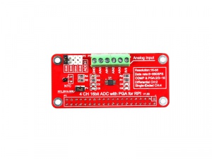
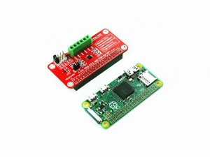
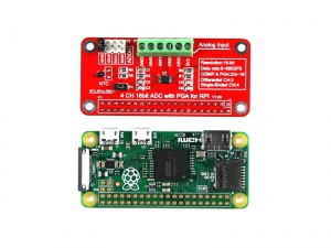
The ADS1115 are precision analog-to-digital converters (ADCs) with 16 bits of resolution offered in an ultra-small, an MSOP-10 package.
Data are transferred via an I2C-compatible serial interface, four I2C slave addresses can be selected, it operate from a single power supply at 3.3V.
It can be used to detect analog signal and convert it to digital signal.
You can attach a joy stick or other analog sensor such as NTC,temperature, dust sensor and so on.
Compatibility List
- Compatibility
| Platform | ADS1115-ADC Module | Notes |
|---|---|---|
| Raspberry Pi 3 Model B Plus | √ | |
| Raspberry Pi zero | √ | |
| Raspberry Pi zero W | √ | |
| Raspberry Pi 3 Model B | √ | |
| Raspberry Pi 2 Model B | √ | |
| Raspberry Pi Model B+ | × |
Features
| Parameters | Values |
|---|---|
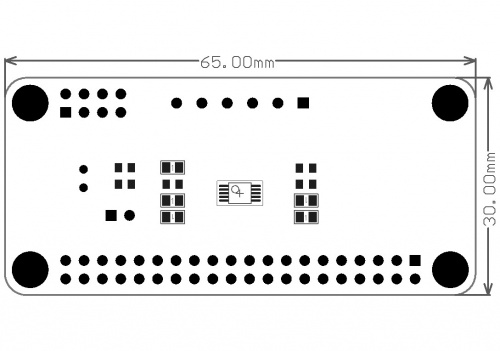
| Size: | 65.0mm x 30.0mm x 18.0mm |
| Power Supply | 3.3v |
| Analog Input Voltage | GND to VDD |
| PROGRAMMABLE DATA RATE: | 8SPS to 860SPS |
| INTERNAL LOW-DRIFT: | VOLTAGE REFERENCE |
| INTERNAL PGA | Available |
| Resolution | 16-bit |
| I2C™ INTERFACE: | Pin-Selectable Addresses |
| Channels Number | 4 SINGLE-ENDED OR 2 DIFFERENTIAL INPUTS |
| PROGRAMMABLE COMPARATOR | 2/3 ~ 16 |
| INTERNAL NTC Support | Available |
Mechanical Drawing
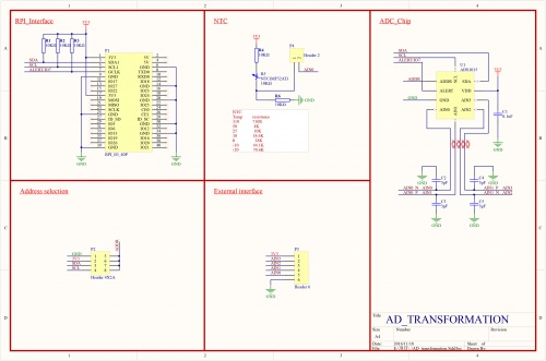
Schematic Diagram
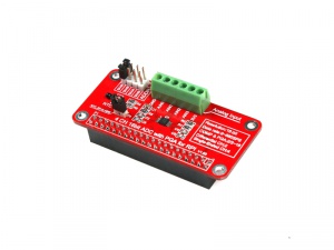
Gallery
How to wire up
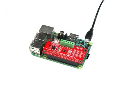
Just Plug into GPIO with this module.
- NOTE: Please be ware of the No.1 Pin is fit for your GPIO No.1 Pin.
How to get analog data
- All steps are available that we've consumed that you have already flashed the newest image file into your TF card, and your RaspberryPi is powered on.
- Modify /boot/config.txt file and add those parameters to enable ADC module's driver:
sudo vim.tiny /boot/config.txt
dtparam=i2c_arm=on
Save it and reboot your raspberry Pi.
- Python code to use the ADS1015 and ADS1115 analog to digital converters with a Raspberry Pi or BeagleBone black.
- To install the library from source (recommended) run the following commands on a Raspberry Pi or other Debian-based OS system:
sudo apt-get install git build-essential python-dev
cd ~
git clone https://github.com/adafruit/Adafruit_Python_ADS1x15.git
cd Adafruit_Python_ADS1x15
sudo python setup.py install
- Alternatively you can install from pip with:
sudo pip install adafruit-ads1x15
- Change your work directory to Adafruit_Python_ADS1x15/example as following command:
cd ~/Adafruit_Python_ADS1x15/examples
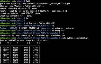
sudo python simpletest.py
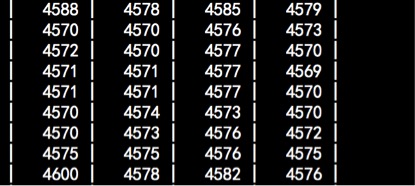
- You will see a chart like following picture:
- Do not panic when you see this picture:
- Remove the jumper from NTC_EN to AIN0, it will be back to normal.
Have fun!
Official Documents
- Datasheet:
FAQ
- Question: how to detect this module's address ?
- Answer: open a terminal and use this command :
- Answer: open a terminal and use this command :
i2cdetect -y 1
You will see the address of your ADS1115's address, by the way, you'd better enable i2c function first.
