EP-0075: Difference between revisions
| (14 intermediate revisions by the same user not shown) | |||
| Line 1: | Line 1: | ||
=RPI-RGB-LED-Matrix= | =RPI-RGB-LED-Matrix= | ||
==Description== | ==Description== | ||
8x8 RGB LED Matrix is based on driver chip to communicate with MCU or SBC via using SPI protocol. It can be used to build variable projects such as music spectrum analyzer, bicycle taillights, Robots, and so on. | |||
The driver chip is a high speed CMOS device. An eight-bit shift register accepts data from the serial input (DS) on each positive transition of the shift register clock (SHCP). When asserted low the reset function () sets all shift register values to zero and is indecent of all clocks. Data from the input serial shift register is placed in the output register with a rising pulse on the storages resister clock (STCP). With the output enable (E asserted low the 3-state outputs Q0-Q7 become active and present the All registers capture data on rising edge and change output on the falling edge. If both clocks are connected together the input shift register is always one clock cycle ahead of the output register. | |||
Using driver chip can greatly save GPIO pins and facilitate programming. | |||
---- | ---- | ||
==Compatibility List== | ==Compatibility List== | ||
* Compatibility | * Compatibility | ||
| Line 11: | Line 14: | ||
|- | |- | ||
!Platform !! Screen and driver board !! Notes | !Platform !! Screen and driver board !! Notes | ||
|- | |||
|Raspberry Pi 4 Model B || √|| | |||
|- | |- | ||
|Raspberry Pi 3 Model B Plus|| √|| | |Raspberry Pi 3 Model B Plus|| √|| | ||
| Line 21: | Line 26: | ||
|- | |- | ||
|Arduino || √|| | |Arduino || √|| | ||
|- | |||
|Raspberry Pi Pico/ Pico W|| √|| | |||
|- | |- | ||
|} | |} | ||
==Feature== | ==Feature== | ||
* Support SPI protocol | * Support SPI protocol | ||
* Low power consumption | * Low power consumption | ||
* RGB three-color combination can be a lot of bright colors | * RGB three-color combination can be a lot of bright colors | ||
-- | * Save GPIO pins | ||
== | * Easy to setup and programming | ||
* Input 3.3V~5V tolerant | |||
* Support speed can be up to 500Kbps | |||
<br><font color=red> | |||
Attention: | |||
Due to technical components, please do not hand touch when it connected to MCU or SBC during it’s running. DO NOT mistake the positive and negative poles, otherwise it will damage the equipment! | |||
</font> | |||
==Product Specifications:== | |||
* Dot size: 5.0mm | |||
* Pixel Array: 8x8 | |||
* Luminous Intensity: 40mcd | |||
* Package Dimension: 60mmx60mm | |||
* Reverse Voltage(Max): 5V | |||
* Forward Current(Max): 25mA | |||
* Peak Forward Current(Max); 100mA | |||
* Power Dissipation(Max): 100mW | |||
* Operating Temperature(Max): -35~+85℃ | |||
* Storage Temperature(Max): -35~+85℃ | |||
* Lead Solder Temperature(Max): 260℃ for 5 seconds | |||
* Colors: R/G/B | |||
* Communication Protocol: SPI | |||
==Gallery== | |||
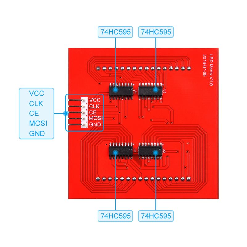
* Pinout | |||
** VCC: Power Input, from 3.3V~5V tolerant | |||
** CLK: SPI Clock Pin | |||
** CE: SPI Chip Select Pin | |||
** MOSI: SPI Master Out Slave In | |||
** GND: Ground | |||
[[File:RGBmatrix8下.jpg|right|800px]] | |||
<br style="clear:both;"> | |||
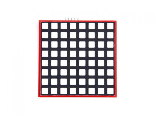
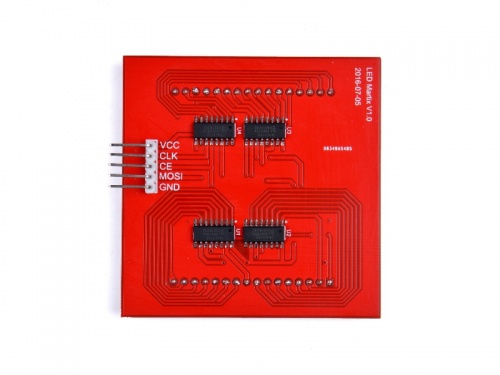
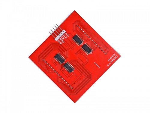
* Product Outlook | |||
{| | {| | ||
|[[File:Matrix1.jpg|left|500px]] | |[[File:Matrix1.jpg|left|500px]] | ||
| Line 43: | Line 80: | ||
==Package includes== | ==Package includes== | ||
* 1x RPI-RGB-LED-Matrix module | * 1x RPI-RGB-LED-Matrix module | ||
---- | ---- | ||
==How to | ==How to use it== | ||
{| class="wikitable" | {| class="wikitable" | ||
! Raspberry Pi !! 8x8 RGB Matrix !! Arduino | ! Raspberry Pi !! 8x8 RGB Matrix !! Arduino | ||
| Line 52: | Line 89: | ||
| 5V ||Vcc || 5v | | 5V ||Vcc || 5v | ||
|- | |- | ||
| | | BCM GPIO 11 || CLK || Pin 13 | ||
|- | |- | ||
| | | BCM GPIO 8 || CE || Pin 10 | ||
|- | |- | ||
| GPIO 10 || MOSI || Pin 11 | | BCM GPIO 10 || MOSI || Pin 11 | ||
|- | |- | ||
| GND ||GND || GND | | GND ||GND || GND | ||
|} | |} | ||
- | ==How to light up LED matrix by using Raspberry Pi == | ||
* We assume that you are using Raspberry Pi OS (64bit) | |||
==How to | * Enable SPI by input following command in a terminal: | ||
* | <pre> | ||
sudo raspi-config | |||
</pre> | |||
and navigate to “Interfacing Options” “P4 SPI” Select and activate “<YES>” | |||
Highlight and activate “<OK>”. When prompted to reboot highlight and activate “<Yes>” . | |||
The Raspberry Pi will reboot and the interface will be enabled. | |||
===How to wire it=== | |||
* Connect 5V from Raspberry Pi 5V Pin to VCC Pin on LED matrix. | |||
* Connect GPIO11 Pin from Raspberry Pi to CLK Pin on LED matrix | |||
* Connect GPIO8 Pin from Raspberry Pi to CE Pin on LED matrix | |||
* Connect GPIO10 Pin from Raspberry Pi to MOSI Pin on LED matrix | |||
* Connect GND Pin from Raspberry Pi to GND Pin on LED matrix | |||
==Configurations== | |||
* After power on and login to system. you can open a terminal and edit /boot/config.txt file to enable SPI function. | |||
<pre> Please according to your Pi model to change the device_tree, for example, i got a raspberry pi 3B, I will change the config.txt's parameter to following code:</pre> | |||
<code>sudo vim.tiny /boot/config.txt </code><br> | <code>sudo vim.tiny /boot/config.txt </code><br> | ||
<pre> | <pre> | ||
| Line 69: | Line 120: | ||
dtparam=spi=on | dtparam=spi=on | ||
</pre> | </pre> | ||
===Python Demo code=== | |||
* | * Create a new file named: matrix.py and then copy following demo code and paste it into the file and execute it. | ||
<pre> | |||
import time | |||
import spidev | |||
# We only have SPI bus 0 available to us on the Pi | |||
bus = 0 | |||
#Device is the chip select pin. Set to 0 or 1, depending on the connections | |||
device = 0 | |||
# Enable SPI | |||
spi = spidev.SpiDev() | |||
# Open a connection to a specific bus and device (chip select pin) | |||
spi.open(bus, device) | |||
# Set SPI speed and mode | |||
spi.max_speed_hz = 500000 | |||
spi.mode = 0 | |||
# setting delay durations | |||
x = 0.5 | |||
# define message information | |||
# msg = [0x00, 0x66, 0xFF, 0xFF, 0xFF, 0x7E, 0x3C, 0x18] | |||
# define method to clear screen. | |||
def clear(): | |||
msg = [0x00, 0x00, 0x00] | |||
spi.xfer2(msg) | |||
time.sleep(x) | |||
# loop | |||
while True: | |||
# define colors | |||
blue = [0x00, 0xff, 0xff] | |||
green = [0xff, 0x00, 0xff] | |||
red = [0xff, 0xff, 0xff] | |||
demo1 = [0xff, 0xAA, 0xff] | |||
demo2 = [0xff, 0x55, 0xff] | |||
spi.xfer2(red) | |||
time.sleep(x) | |||
spi.xfer2(green) | |||
time.sleep(x) | |||
spi.xfer2(blue) | |||
time.sleep(x) | |||
spi.xfer2(demo1) | |||
time.sleep(x) | |||
spi.xfer2(demo2) | |||
time.sleep(x) | |||
clear() | |||
</pre> | |||
save it and execute it: | |||
<pre> | |||
python3 matrix.py | |||
</pre> | |||
===C language Demo code=== | |||
* Create a file named matrix.c and typing following codes: <br> | |||
<code> | <code> | ||
sudo vim.tiny matrix.c | sudo vim.tiny matrix.c | ||
</code><br> | </code><br> | ||
<pre> | <pre> | ||
#include <stdint.h> | |||
#include <unistd.h> | |||
#include <stdio.h> | #include <stdio.h> | ||
#include < | #include <stdlib.h> | ||
#include < | #include <string.h> | ||
#include < | #include <errno.h> | ||
#include <getopt.h> | |||
#include <fcntl.h> | |||
#include <time.h> | |||
#include <sys/ioctl.h> | |||
#include <linux/ioctl.h> | |||
#include <sys/stat.h> | |||
#include <linux/types.h> | |||
#include <linux/spi/spidev.h> | |||
static const char *device = "/dev/spidev0.0"; | |||
static uint8_t bits = 8; // 8bit register for 74hc595 | |||
static uint32_t mode = 0; // set SPI mode | |||
static uint32_t speed = 500000; // set SPI speed in hz 500 kHz | |||
static int interval = 5; // set sending interval 5 cycle. about 30nS. | |||
static uint8_t heart[8] = {0x00, 0x66, 0xFF, 0xFF, 0xFF, 0x7E, 0x3C, 0x18}; // heart shape | |||
static uint8_t default_tx[4] = {0x00,}; | |||
static uint8_t default_rx[4] = {0x00,}; | |||
// error message | |||
static void pabort(const char *s) | |||
{ | |||
if (errno != 0) | |||
perror(s); | |||
else | |||
printf("%s\n", s); | |||
abort(); | |||
} | |||
static void transfer(int fd, uint8_t const *tx, uint8_t const *rx, size_t len) | |||
{ | |||
int ret; | |||
int out_fd; | |||
struct spi_ioc_transfer tr = { | |||
.tx_buf = (unsigned long)tx, | |||
.rx_buf = (unsigned long)rx, | |||
.len = len, | |||
.speed_hz = speed, | |||
.bits_per_word = bits, | |||
}; | |||
// setting to 0 will let system determine transfer bit. | |||
tr.tx_nbits = 0; | |||
tr.rx_nbits = 0; | |||
ret = ioctl(fd, SPI_IOC_MESSAGE(1), &tr); | |||
if (ret < 1) | |||
pabort("can't send spi message"); | |||
} | |||
int main( | int main(int argc, char *argv[]) | ||
{ | { | ||
int ret = 0; | |||
int fd; | |||
uint32_t request; | |||
fd = open(device, O_RDWR); | |||
if (fd < 0) | |||
pabort("can't open device"); | |||
ioctl(fd, SPI_IOC_WR_MODE32, &mode); | |||
for ( j=0;j<8;j++) | |||
{ | // 8bit latch | ||
ret = ioctl(fd, SPI_IOC_WR_BITS_PER_WORD, &bits); | |||
if (ret == -1) | |||
pabort("can't set bits per word"); | |||
// make sure setting is ok. | |||
ret = ioctl(fd, SPI_IOC_RD_BITS_PER_WORD, &bits); | |||
if (ret == -1) | |||
pabort("can't get bits per word"); | |||
// setting speed | |||
ret = ioctl(fd, SPI_IOC_WR_MAX_SPEED_HZ, &speed); | |||
if (ret == -1) | |||
pabort("can't set max speed hz"); | |||
// make sure speed is setting properly. | |||
ret = ioctl(fd, SPI_IOC_RD_MAX_SPEED_HZ, &speed); | |||
if (ret == -1) | |||
pabort("can't get max speed hz"); | |||
for (;;) // loop | |||
{ // sending pattern looply | |||
for (int j = 0; j < 8; j++) | |||
{ '= | |||
default_tx[0] = ~heart[j]; // R- From Pattern Buf | |||
default_tx[2] = 0xFF; // G - All Off - All One | |||
default_tx[1] = 0xFF; // B - All 0ff - All One | |||
default_tx[3] = 0x01 << j; // Col select - draw and fresh | |||
transfer(fd, default_tx, default_rx, sizeof(default_tx)); // sending data to spi device. | |||
usleep(2 * 1000); // delay for a while | |||
}; | }; | ||
}; | } | ||
}</pre> | close(fd); // close file description | ||
* | return ret; | ||
} | |||
</pre> | |||
* Compile it and run: | |||
<pre> | |||
gcc -o matrix matrix.c | |||
./matrix | |||
</pre> | |||
==Other Examples== | ==Other Examples== | ||
| Line 351: | Line 531: | ||
Then, You will see this:<br> | Then, You will see this:<br> | ||
[[File:Arduino.gif |left| 300px ]] | [[File:Arduino.gif |left| 300px ]] | ||
<br style="clear:both;"> | |||
==How to light it up with Raspberry Pi Pico== | |||
* Build circuit according to following chart: | |||
{| class="wikitable" | |||
|- | |||
! Raspberry Pi Pico !! 8x8 RGB Matrix | |||
|- | |||
| 5V || VCC | |||
|- | |||
| GND || GND | |||
|- | |||
| GP2 || CLK | |||
|- | |||
| GP3 || MOSI | |||
|- | |||
| GP4 || Do not connect | |||
|- | |||
| GP5 || CE | |||
|} | |||
* Open thonny IDE and upload following code to Raspberry Pi Pico. | |||
<pre> | |||
from machine import Pin, SPI | |||
from time import sleep | |||
RED = 0 | |||
BLUE = 1 | |||
GREEN = 2 | |||
bus = SPI(0, baudrate=500000, polarity=1, phase=1, bits=8, sck=Pin(2), mosi=Pin(3), miso=Pin(4)) | |||
print(bus) | |||
CE = Pin(5, Pin.OUT) | |||
data = bytearray([0,0,0,0]) | |||
#heart = [0x00, 0x66, 0xff,0xff,0xff, 0x7e, 0x3c, 0x18] | |||
alien = [0xC3, 0x42, 0x3C, 0x42, 0xA5, 0x5A, 0x7E, 0x81] | |||
alien2 = [0xC3, 0x42, 0x3C, 0x42, 0x99, 0x42, 0x66, 0x99] | |||
CE.value(0) | |||
while True: | |||
for j in range(0, 8): | |||
data[0] = ~alien[j] #red | |||
data[1] = 0xff # blue | |||
data[2] = 0xff # green | |||
data[3] = 0x01 << j # COM, GND | |||
CE.value(0) | |||
bus.write(bytearray(data)) | |||
#bus.write_readinto(bytearray(data), bytearray(4)) | |||
CE.value(1) | |||
sleep(0.001) | |||
for j in range(0, 8): | |||
data[0] = 0xff | |||
data[1] = ~alien2[j] | |||
data[2] = 0xff | |||
data[3] = 0x01 << j | |||
CE.value(0) | |||
bus.write(bytearray(data)) | |||
CE.value(1) | |||
sleep(0.001) | |||
</pre> | |||
[[File:Picomatrix185324.jpg|left|500px]] | |||
<br style="clear:both;"> | <br style="clear:both;"> | ||
==Application | ==Application Scenario== | ||
* There is a link below shown that we made an E-Bike with this 8*8 RGB LED matrix during Maker Fair. | * There is a link below shown that we made an E-Bike with this 8*8 RGB LED matrix during Maker Fair. | ||
[Voice-Prompt-Electric-Bike | https://www.instructables.com/id/Voice-Prompt-Electric-Bike/ ] | [Voice-Prompt-Electric-Bike | https://www.instructables.com/id/Voice-Prompt-Electric-Bike/ ] | ||
---- | ---- | ||
Latest revision as of 17:09, 1 February 2023
RPI-RGB-LED-Matrix
Description
8x8 RGB LED Matrix is based on driver chip to communicate with MCU or SBC via using SPI protocol. It can be used to build variable projects such as music spectrum analyzer, bicycle taillights, Robots, and so on.
The driver chip is a high speed CMOS device. An eight-bit shift register accepts data from the serial input (DS) on each positive transition of the shift register clock (SHCP). When asserted low the reset function () sets all shift register values to zero and is indecent of all clocks. Data from the input serial shift register is placed in the output register with a rising pulse on the storages resister clock (STCP). With the output enable (E asserted low the 3-state outputs Q0-Q7 become active and present the All registers capture data on rising edge and change output on the falling edge. If both clocks are connected together the input shift register is always one clock cycle ahead of the output register.
Using driver chip can greatly save GPIO pins and facilitate programming.
Compatibility List
- Compatibility
| Platform | Screen and driver board | Notes |
|---|---|---|
| Raspberry Pi 4 Model B | √ | |
| Raspberry Pi 3 Model B Plus | √ | |
| Raspberry Pi 3 Model B | √ | |
| Raspberry Pi 2 Model B | √ | |
| Raspberry Pi zero/ zero w | √ | |
| Arduino | √ | |
| Raspberry Pi Pico/ Pico W | √ |
Feature
- Support SPI protocol
- Low power consumption
- RGB three-color combination can be a lot of bright colors
- Save GPIO pins
- Easy to setup and programming
- Input 3.3V~5V tolerant
- Support speed can be up to 500Kbps
Attention:
Due to technical components, please do not hand touch when it connected to MCU or SBC during it’s running. DO NOT mistake the positive and negative poles, otherwise it will damage the equipment!
Product Specifications:
- Dot size: 5.0mm
- Pixel Array: 8x8
- Luminous Intensity: 40mcd
- Package Dimension: 60mmx60mm
- Reverse Voltage(Max): 5V
- Forward Current(Max): 25mA
- Peak Forward Current(Max); 100mA
- Power Dissipation(Max): 100mW
- Operating Temperature(Max): -35~+85℃
- Storage Temperature(Max): -35~+85℃
- Lead Solder Temperature(Max): 260℃ for 5 seconds
- Colors: R/G/B
- Communication Protocol: SPI
Gallery
- Pinout
- VCC: Power Input, from 3.3V~5V tolerant
- CLK: SPI Clock Pin
- CE: SPI Chip Select Pin
- MOSI: SPI Master Out Slave In
- GND: Ground
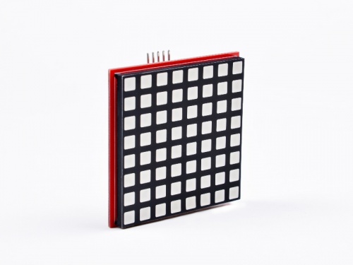
- Product Outlook
Package includes
- 1x RPI-RGB-LED-Matrix module
How to use it
| Raspberry Pi | 8x8 RGB Matrix | Arduino |
|---|---|---|
| 5V | Vcc | 5v |
| BCM GPIO 11 | CLK | Pin 13 |
| BCM GPIO 8 | CE | Pin 10 |
| BCM GPIO 10 | MOSI | Pin 11 |
| GND | GND | GND |
How to light up LED matrix by using Raspberry Pi
- We assume that you are using Raspberry Pi OS (64bit)
- Enable SPI by input following command in a terminal:
sudo raspi-config
and navigate to “Interfacing Options” “P4 SPI” Select and activate “<YES>” Highlight and activate “<OK>”. When prompted to reboot highlight and activate “<Yes>” . The Raspberry Pi will reboot and the interface will be enabled.
How to wire it
- Connect 5V from Raspberry Pi 5V Pin to VCC Pin on LED matrix.
- Connect GPIO11 Pin from Raspberry Pi to CLK Pin on LED matrix
- Connect GPIO8 Pin from Raspberry Pi to CE Pin on LED matrix
- Connect GPIO10 Pin from Raspberry Pi to MOSI Pin on LED matrix
- Connect GND Pin from Raspberry Pi to GND Pin on LED matrix
Configurations
- After power on and login to system. you can open a terminal and edit /boot/config.txt file to enable SPI function.
Please according to your Pi model to change the device_tree, for example, i got a raspberry pi 3B, I will change the config.txt's parameter to following code:
sudo vim.tiny /boot/config.txt
   device_tree=bcm2710-rpi-3-b.dtb
   dtparam=spi=on
Python Demo code
- Create a new file named: matrix.py and then copy following demo code and paste it into the file and execute it.
import time
import spidev

# We only have SPI bus 0 available to us on the Pi
bus = 0

#Device is the chip select pin. Set to 0 or 1, depending on the connections
device = 0

# Enable SPI
spi = spidev.SpiDev()

# Open a connection to a specific bus and device (chip select pin)
spi.open(bus, device)

# Set SPI speed and mode
spi.max_speed_hz = 500000
spi.mode = 0

# setting delay durations
x = 0.5
# define message information
# msg = [0x00, 0x66, 0xFF, 0xFF, 0xFF, 0x7E, 0x3C, 0x18]
# define method to clear screen.
def clear():
    msg = [0x00, 0x00, 0x00]
    spi.xfer2(msg)
    time.sleep(x)

# loop
while True:
    # define colors
    blue = [0x00, 0xff, 0xff]
    green = [0xff, 0x00, 0xff]
    red = [0xff, 0xff, 0xff]
    demo1 = [0xff, 0xAA, 0xff]
    demo2 = [0xff, 0x55, 0xff]

    spi.xfer2(red)
    time.sleep(x)
    spi.xfer2(green)
    time.sleep(x)
    spi.xfer2(blue)
    time.sleep(x)
    spi.xfer2(demo1)
    time.sleep(x)
    spi.xfer2(demo2)
    time.sleep(x)
    clear()
save it and execute it:
python3 matrix.py
C language Demo code
- Create a file named matrix.c and typing following codes:
sudo vim.tiny matrix.c
#include <stdint.h>
#include <unistd.h>
#include <stdio.h>
#include <stdlib.h>
#include <string.h>
#include <errno.h>
#include <getopt.h>
#include <fcntl.h>
#include <time.h>
#include <sys/ioctl.h>
#include <linux/ioctl.h>
#include <sys/stat.h>
#include <linux/types.h>
#include <linux/spi/spidev.h>

static const char *device = "/dev/spidev0.0";
static uint8_t bits = 8; // 8bit register for 74hc595
static uint32_t mode = 0; //  set SPI mode
static uint32_t speed = 500000; // set SPI speed in hz 500 kHz
static int interval = 5; // set sending interval 5 cycle. about 30nS.

static uint8_t heart[8] = {0x00, 0x66, 0xFF, 0xFF, 0xFF, 0x7E, 0x3C, 0x18};  // heart shape
static uint8_t default_tx[4] = {0x00,};
static uint8_t default_rx[4] = {0x00,};

// error message
static void pabort(const char *s)
{
    if (errno != 0)
        perror(s);
    else
        printf("%s\n", s);

    abort();
}

static void transfer(int fd, uint8_t const *tx, uint8_t const *rx, size_t len)
{
        int ret;
        int out_fd;
        struct spi_ioc_transfer tr = {
                .tx_buf = (unsigned long)tx,
                .rx_buf = (unsigned long)rx,
                .len = len,
                .speed_hz = speed,
                .bits_per_word = bits,
        };

    // setting to 0 will let system determine transfer bit.
    tr.tx_nbits = 0;
    tr.rx_nbits = 0;

        ret = ioctl(fd, SPI_IOC_MESSAGE(1), &tr);
        if (ret < 1)
                pabort("can't send spi message");
}

int main(int argc, char *argv[])
{
    int ret = 0;
    int fd;
    uint32_t request;

    fd = open(device, O_RDWR);
    if (fd < 0)
        pabort("can't open device");

    ioctl(fd, SPI_IOC_WR_MODE32, &mode);

    // 8bit latch
    ret = ioctl(fd, SPI_IOC_WR_BITS_PER_WORD, &bits);
    if (ret == -1)
        pabort("can't set bits per word");
    // make sure setting is ok.
    ret = ioctl(fd, SPI_IOC_RD_BITS_PER_WORD, &bits);
    if (ret == -1)
        pabort("can't get bits per word");

    // setting speed
    ret = ioctl(fd, SPI_IOC_WR_MAX_SPEED_HZ, &speed);
    if (ret == -1)
        pabort("can't set max speed hz");
    // make sure speed is setting properly.
    ret = ioctl(fd, SPI_IOC_RD_MAX_SPEED_HZ, &speed);
    if (ret == -1)
        pabort("can't get max speed hz");

    for (;;)  // loop
    {   // sending pattern looply
        for (int j = 0; j < 8; j++)
        {  '=
            default_tx[0] = ~heart[j];  // R- From Pattern Buf
            default_tx[2] = 0xFF;       // G - All Off - All One
            default_tx[1] = 0xFF;       // B - All 0ff - All One
            default_tx[3] = 0x01 << j;  // Col select - draw and fresh
            transfer(fd, default_tx, default_rx, sizeof(default_tx));  // sending data to spi device.
            usleep(2 * 1000);   // delay for a while
        };
    }
    close(fd);   // close file description
    return ret;
}
- Compile it and run:
gcc -o matrix matrix.c
./matrix
Other Examples
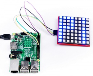
There are some pictures here:
- 1. Static Heart Sign
#include <stdio.h>
#include <wiringPi.h>
#include <wiringPiSPI.h>
#include <stdint.h>

#define RED_DATA 0          //define the red data source
#define BLUE_DATA 1         //define the blue data source
#define GREEN_DATA 2    // define the green data source

int main(void)
{
  static uint8_t data[4] = {0x0,0x0,0x0,0x0};                  // initialize RGB data source
  static uint8_t i = 0;

  wiringPiSetup();                                // initialize wiringPi
  wiringPiSPISetup(0,500000);           // initialize SPI  information, 0 is channel 0, 500000 is clock rate.
  while(1){
    int j;
    int x = 2;
    static uint8_t heart[8] = {0x00, 0x66, 0xFF, 0xFF, 0xFF, 0x7E, 0x3C, 0x18};             // this is a array of heart
    for ( j=0;j<8;j++)
{
          data[0] = ~heart[j];
          data[2] = 0xFF;
          data[1] = 0xFF;
          data[3] = 0x01 << j ;
          wiringPiSPIDataRW(0,data,sizeof(data));              // send data to SPI channel 0, and the length of the data
          delay(x);
   }
  }
}
- 2. heart beating:
All you need to do is copy following codes to a file named heart.c , and save it, and then compile it.
sudo vim.tiny heart.c
#include <stdio.h>
#include <wiringPi.h>
#include <wiringPiSPI.h>
#include <stdint.h>

#define RED_DATA 0
#define BLUE_DATA 1
#define GREEN_DATA 2

int main(void)
{
  static uint8_t data[4] = {0x0,0x0,0x0,0x0};
  static uint8_t i = 0;

  wiringPiSetup();
  wiringPiSPISetup(0,500000);

void heartbig()
   {
    int j;
    int x = 2;
    static uint8_t heart[8] = {0x00, 0x66, 0xFF, 0xFF, 0xFF, 0x7E, 0x3C, 0x18};
    for ( j=0;j<8;j++)
                {
          data[0] = ~heart[j];
          data[2] = 0xFF;
          data[1] = 0xFF;
          data[3] = 0x01 << j ;
          wiringPiSPIDataRW(0,data,sizeof(data));
          delay(x);
                }
};

void heartsmall()
   {
    int j;
    int x = 2;
    static uint8_t heart[8] = {0x00, 0x00, 0x24, 0x7E, 0x7E, 0x3C, 0x18, 0x00};
    for ( j=0;j<8;j++)
                {
          data[0] = ~heart[j];
          data[2] = 0xFF;
          data[1] = 0xFF;
          data[3] = 0x01 << j ;
          wiringPiSPIDataRW(0,data,sizeof(data));
          delay(x);
                }
};

void matrixoff()
{
 int j;
 int x = 2;
    static uint8_t heart[8] = {0x00, 0x00, 0x00, 0x00, 0x00, 0x00, 0x00, 0x00};
    for ( j=0;j<8;j++)
     {
          data[0] = ~heart[j];
          data[2] = 0xFF;
          data[1] = 0xFF;
          data[3] = 0x01 << j ;
          wiringPiSPIDataRW(0,data,sizeof(data));
          delay(x);
       }
}

while(1){
     int m = 10;
     for ( m=10; m>0; m--)
        {
         heartbig();
         };
         matrixoff();
        delay(100);
     for ( m=10; m>0; m--)
         {
         heartsmall();
         };
         matrixoff();
         delay(100);
    }
}
- 2. Compile it and run it.
sudo gcc -o heart heart.c -lwiringPi
sudo ./heart
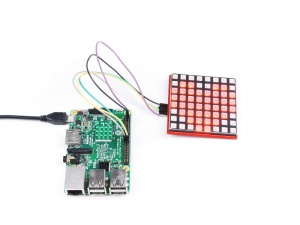
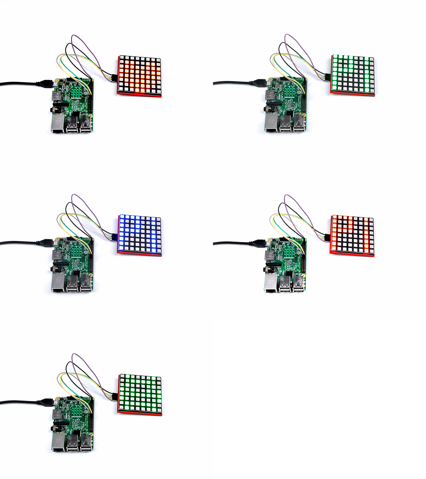
You will see a view like this:
How to use Arduino to light up 8x8 matrix
- 1. Open an Arduino IDE and paste this code and upload to your Arduino board.
#include <SPI.h>                  //  include the head file to enable the  library.

static uint8_t data[4] = {0x0, 0x0, 0x0, 0x0};         // defined a data matrix
static uint8_t i = 1;                                                    // defined a variable vector
const int CE = 10;                                                      // defined  the CE function pin

void heartbig()                                                  // defined a function called "heart big".
{
  int j;
  int x = 2;
  static uint8_t heart[8] = {0x00, 0x66, 0xFF, 0xFF, 0xFF, 0x7E, 0x3C, 0x18};    // you need to calculate which led should be light up by this array, it defined line by line on your matrix, for example , 0x00 means the led of the first line is off,  and the 0x66 means the second line's first led will go off and the fourth led will go off and fifth led will go off and eight led will go off. others will turn on....and so on.

  for ( j = 0; j < 8; j++)
  {
    data[0] = ~heart[j];       // color red
    data[2] = 0xFF;             // color green
    data[1] = 0xFF;             // color blue
    data[3] = 0x01 << j ;    // display the data on matrix.
    digitalWrite(CE, LOW);     // when CE is low, it begin to receive data.
    SPI.transfer(data[0]);         //transfer data[0] to the matrix(red)
    SPI.transfer(data[2]);         //transfer data[2] to the matrix(green)
    SPI.transfer(data[1]);        // transfer   data[1] to the matrix(blue)
    SPI.transfer(data[3]);      // tansfer data[3] to the matrix( scanning and display the data on matrix)
    digitalWrite(CE, HIGH);    // when CE is High, means that matrix begin to display the array's information to the matrix.
    delay(x);                          // a little bit delay, let the led light up and stay for a while so that it looks like it brightness.
  }
};

void heartsmall()
{
  int j;
  int x = 2;
  static uint8_t heart[8] = {0x00, 0x00, 0x24, 0x7E, 0x7E, 0x3C, 0x18, 0x00};          // change the hard to be the smaller one, all you need to do is change this parameter.
  for ( j = 0; j < 8; j++)
  {
    data[0] = ~heart[j];
    data[2] = 0xFF;
    data[1] = 0xFF;
    data[3] = 0x01 << j ;
    digitalWrite(CE, LOW);
    SPI.transfer(data[0]);
    SPI.transfer(data[2]);
    SPI.transfer(data[1]);
    SPI.transfer(data[3]);
    digitalWrite(CE, HIGH);
    delay(x);
  }
};

void matrixoff()
{
  int j;
  int x = 2;
  static uint8_t heart[8] = {0x00, 0x00, 0x00, 0x00, 0x00, 0x00, 0x00, 0x00};        // you can see, all of the led will go off here.
  for ( j = 0; j < 8; j++)
  {
    data[0] = ~heart[j];
    data[2] = 0xFF;
    data[1] = 0xFF;
    data[3] = 0x01 << j ;
    digitalWrite(CE, LOW);
    SPI.transfer(data[0]);
    SPI.transfer(data[2]);
    SPI.transfer(data[1]);
    SPI.transfer(data[3]);
    digitalWrite(CE, HIGH);
    delay(x);
  }
};

void setup() {
  pinMode(CE, OUTPUT);                          //initialized the pin's mode.
  SPI.begin();                                              // start spi function
}

void loop()                                                  //defined a loop function
{
  int m = 10;
  for ( m = 10; m > 0; m--) {                     // make a for loop to let the data displayed on the matrix.
    heartbig();
  };
  matrixoff();                                          // turn off the matrix
  delay(100);                                         // delay 100 ms
  for ( m = 10; m > 0; m--) {                 // let the data displayed on the matrix
    heartsmall();
  };
  matrixoff();
  delay(100);
}
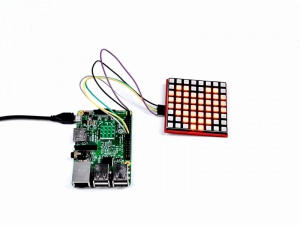
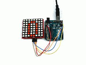
Then, You will see this:
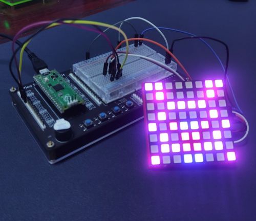
How to light it up with Raspberry Pi Pico
- Build circuit according to following chart:
| Raspberry Pi Pico | 8x8 RGB Matrix |
|---|---|
| 5V | VCC |
| GND | GND |
| GP2 | CLK |
| GP3 | MOSI |
| GP4 | Do not connect |
| GP5 | CE |
- Open thonny IDE and upload following code to Raspberry Pi Pico.
from machine import Pin, SPI
from time import sleep

RED = 0
BLUE = 1
GREEN = 2

bus = SPI(0, baudrate=500000, polarity=1, phase=1, bits=8, sck=Pin(2), mosi=Pin(3), miso=Pin(4))
print(bus)
CE = Pin(5, Pin.OUT)
data = bytearray([0,0,0,0])
#heart = [0x00, 0x66, 0xff,0xff,0xff, 0x7e, 0x3c, 0x18]
alien = [0xC3, 0x42, 0x3C, 0x42, 0xA5, 0x5A, 0x7E, 0x81]
alien2 = [0xC3, 0x42, 0x3C, 0x42, 0x99, 0x42, 0x66, 0x99]
CE.value(0)
while True:

    for j in range(0, 8):
        data[0] = ~alien[j] #red
        data[1] = 0xff      # blue
        data[2] = 0xff      # green
        data[3] = 0x01 << j # COM, GND

        CE.value(0)
        bus.write(bytearray(data))
        #bus.write_readinto(bytearray(data), bytearray(4))
        CE.value(1)
        sleep(0.001)
    for j in range(0, 8):
        data[0] = 0xff
        data[1] = ~alien2[j]
        data[2] = 0xff
        data[3] = 0x01 << j
        CE.value(0)
        bus.write(bytearray(data))
        CE.value(1)
        sleep(0.001)
Application Scenario
- There is a link below shown that we made an E-Bike with this 8*8 RGB LED matrix during Maker Fair.
[Voice-Prompt-Electric-Bike | https://www.instructables.com/id/Voice-Prompt-Electric-Bike/ ]
