EP-0099: Difference between revisions
| Line 38: | Line 38: | ||
==Package include== | ==Package include== | ||
* 1x 4 Channel Relay | * 1x Docker Pi 4 Channel Relay | ||
* 1x Instructions | * 1x Instructions | ||
* 4x M2.5*12 + 6 Copper stick | |||
* 4x M2.5*6 Nut | |||
* 4x M2.5*6 Half-round head screw | |||
[[File:Ddl-4.jpg|left|300px]] | [[File:Ddl-4.jpg|left|300px]] | ||
<br style="clear:both;" > | <br style="clear:both;" > | ||
Revision as of 11:48, 27 June 2019
4 Channel Relay Hat Board For Raspberry Pi
Description
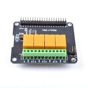
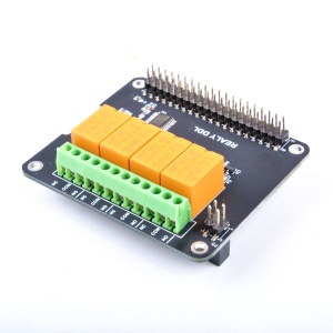
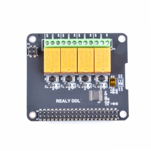
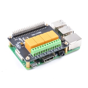
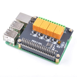
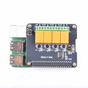
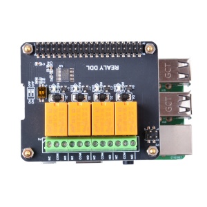
4 Channel Relay Hat Board For Raspberry Pi is one of the "docker pi" module.
It has 4 channel relay that you can put it on your smart home project.
This four-channel relay uses high-quality relay modules combined with
the most popular microcontroller technology to communicate with the Raspberry Pi.
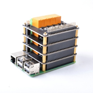
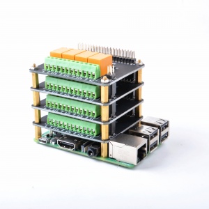
You can use multiple modules stacked together for use.
You can stack up to four layers.
Switch the I2C address of the device through the DIP switch on the circuit board to ensure that
the four-layer module gets different addresses, thus avoiding the problem of address duplication.
The module is very fast, easy to install, and supports multi-language development, making it ideal for smart home projects.
Features
- DockerPi Series
- Programmable
- Control directly(without programming)
- Extend the GPIO Pins
- 4 Channel Relay
- 4 Alt I2C Addr Support
- Relay Status Leds
- Support 3A 250V AC
- Support 3A 30V DC
- Can Stack with other Stack board
- Independent of the mainboard hardware (require I2C support)
Official Compatibility Test
Not only support the following development boards, other development boards can be compatible if they have I2C peripherals. (Note: some software changes may be required)
| Platform | DockerPi Nightlight | Notes |
|---|---|---|
| Raspberry Pi All Platform | √ | Not Include CM Series & EOL Platform |
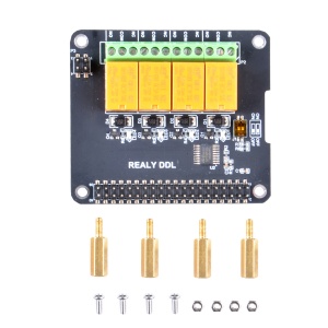
Package include
- 1x Docker Pi 4 Channel Relay
- 1x Instructions
- 4x M2.5*12 + 6 Copper stick
- 4x M2.5*6 Nut
- 4x M2.5*6 Half-round head screw
Device Address Map
| DIP switch status icon | Device Address |
|---|---|
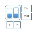 |
0x10 |
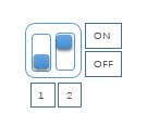 |
0x11 |
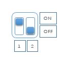 |
0x12 |
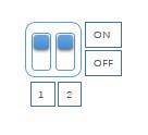 |
0x13 |
Gallery
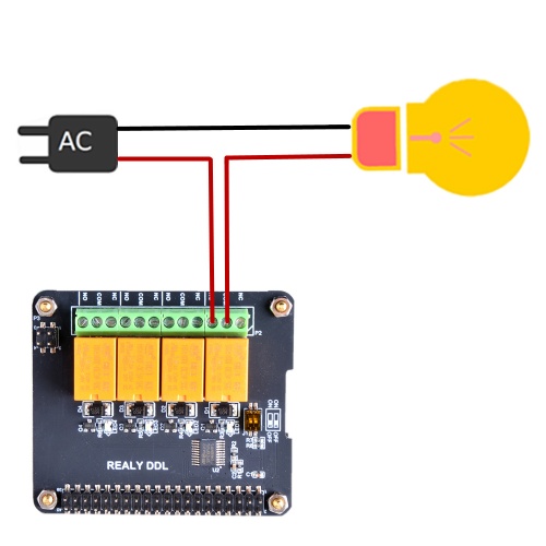
How to connect electrical device
- Caution: If the wrong cable is connected, it may cause fire or personal injury.
- Please pay attention to disconnect the power when connecting the cable and ensure the wiring is correct!
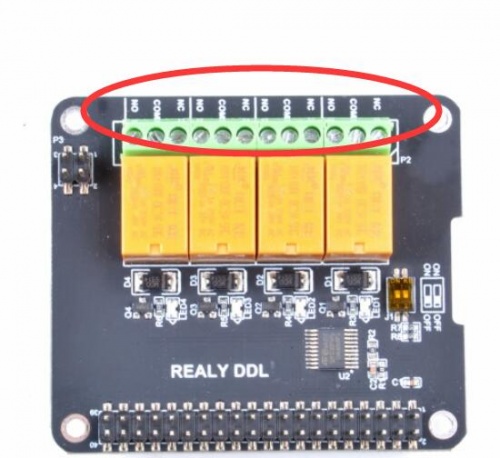
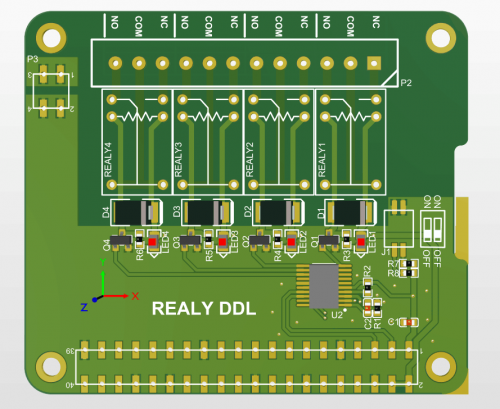
Please pay attension to this mark on the board:
- NC means Normal Close
- COM means Earth or GND
- NO means Normal Open
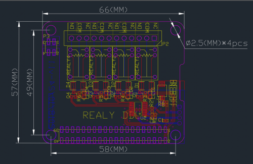
Mechanical Drawing
- PCB Information
- Dimension Information
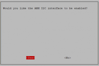
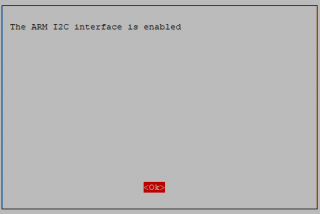
Configuring I2C(Raspberry Pi)
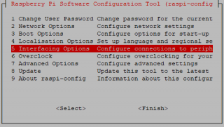
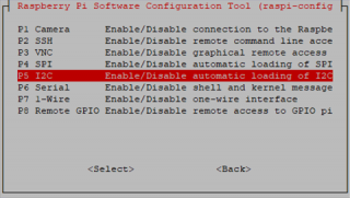
Run sudo raspi-config and follow the prompts to install i2c support for the ARM core and linux kernel
Go to Interfacing Options
then I2C
Enable!
Done!
Demo code
- Turn on channel No.1 relay
i2cset -y 1 0x10 0x01 0xFF
- Turn off channel No.1 relay
i2cset -y 1 0x10 0x01 0x00
- Turn on channel No.2 relay
i2cset -y 1 0x10 0x02 0xFF
- Turn off channel No.2 relay
i2cset -y 1 0x10 0x02 0x00
- Turn on channel No.3 relay
i2cset -y 1 0x10 0x03 0xFF
- Turn off channel No.3 relay
i2cset -y 1 0x10 0x03 0x00
- Turn on channel No.4 relay
i2cset -y 1 0x10 0x04 0xFF
- Turn off channel No.4 relay
i2cset -y 1 0x10 0x04 0x00
- Program in Shell script
Create a file and name it "relay.sh"
#!/bin/bash
# create a loop to turn each relay on and off.
while true
do
   for i in `seq 1 4`
   do
      i2cset -y 1 0x10 $i 0xff
      sleep 1
      i2cset -y 1 0x10 $i 0x00
      sleep 1
   done
done
Then add executive permission to the script:
chmod +x relay.sh
./relay.sh
Program in Language C
Create source code and name it "relay.c"
#include <stdio.h>
#include <wiringPi.h>
#include <wiringPiI2C.h>

#define DEVCIE_ADDR  0x10
#define RELAY1  0x01
#define RELAY2  0x02
#define RELAY3  0x03
#define RELAY4  0x04
#define ON      0xFF
#define OFF     0x00

int main(void){
    printf("Turn on Relays in C\n");
    int fd;
    int i = 0;
    fd = wiringPiI2CSetup(DEVICE_ADDR);
    for(;;){
       for (i=1; i<=4; i++){
          printf("turn on relay No.$d", i);
          wiringPiI2CWriteReg8(fd, i, ON);
          sleep(200);
          printf("turn off relay No.$d", i);
          wiringPiI2CWriteReg8(fd, i, OFF);
          sleep(200);
       }
    }
    return 0;
}
- Compile it with following command:
gcc relay.c -lwiringPi -o relay
- run it
./relay
Program in Python
- Copy and paste following code to a file named relay.py
#!/usr/bin/python3
#
import time as t
import smbus

DEVICE_BUS = 1
DEVICE_ADDR = 0x10
bus = smbus.SMBus(DEVICE_BUS)

while True:
    try:
        for i in range(1,5):
            bus.write_byte_data(DEVICE_ADDR, i, 0xFF)
            t.sleep(1)
            bus.write_byte_data(DEVICE_ADDR, i, 0x00)
            t.sleep(1)
    except KeyboardInterrupt as e:
        print("Quit the Loop")
save it and run:
chmod +x relay.py
./relay.py
Program in Java
- Create a new file named: I2CRelay.java and paste following code:
import java.io.IOException;
import java.util.Arrays;

import com.pi4j.io.i2c.I2CBus;
import com.pi4j.io.i2c.I2CDevice;
import com.pi4j.io.i2c.I2CFactory;
import com.pi4j.io.i2c.I2CFactory.UnsupportedBusNumberException;
import com.pi4j.platform.PlatformAlreadyAssignedException;
import com.pi4j.util.Console;

public class I2CRelay {

    // relay's register address.
    public static final int DOCKER_PI_RELAY_ADDR = 0x10;

    // channel of relay.
    public static final byte DOCKER_PI_RELAY_1 = (byte)0x01;
    public static final byte DOCKER_PI_RELAY_2 = (byte)0x02;
    public static final byte DOCKER_PI_RELAY_3 = (byte)0x03;
    public static final byte DOCKER_PI_RELAY_4 = (byte)0x04;

    // Relay status
    public static final byte DOCKER_PI_RELAY_ON = (byte)0xFF;
    public static final byte DOCKER_PI_RELAY_OFF = (byte)0x00;

    public static void main(String[] args) throws InterruptedException, PlatformAlreadyAssignedException, IOException, UnsupportedBusNumberException {

        final Console console = new Console();

        I2CBus i2c = I2CFactory.getInstance(I2CBus.BUS_1);
        I2CDevice device = i2c.getDevice(DOCKER_PI_RELAY_ADDR);

        console.println("Turn on Relay!");
        device.write(DOCKER_PI_RELAY_1, DOCKER_PI_RELAY_ON);

        Thread.sleep(500);

        console.println("Turn off Relay!");
        device.write(DOCKER_PI_RELAY_1, DOCKER_PI_RELAY_OFF);
    }
}
- Compile it and running:
javac I2CRelay.java -classpath .:classes:/opt/pi4j/lib/'*'
sudo java -classpath .:classes:/opt/pi4j/lib/'*' I2CRelay
- Code Download: File:I2CRelay.zip
Git Repository
You can also clone the repository from github:
sudo apt-get update
sudo apt-get -y install git
git clone https://github.com/geeekpi/dockerpi
cd dockerpi/
Running Differenet program with different way.
