EP-0152
Raspberry Pi Fan Expansion Board Plus 0.91 OLED V1.0
Description
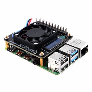
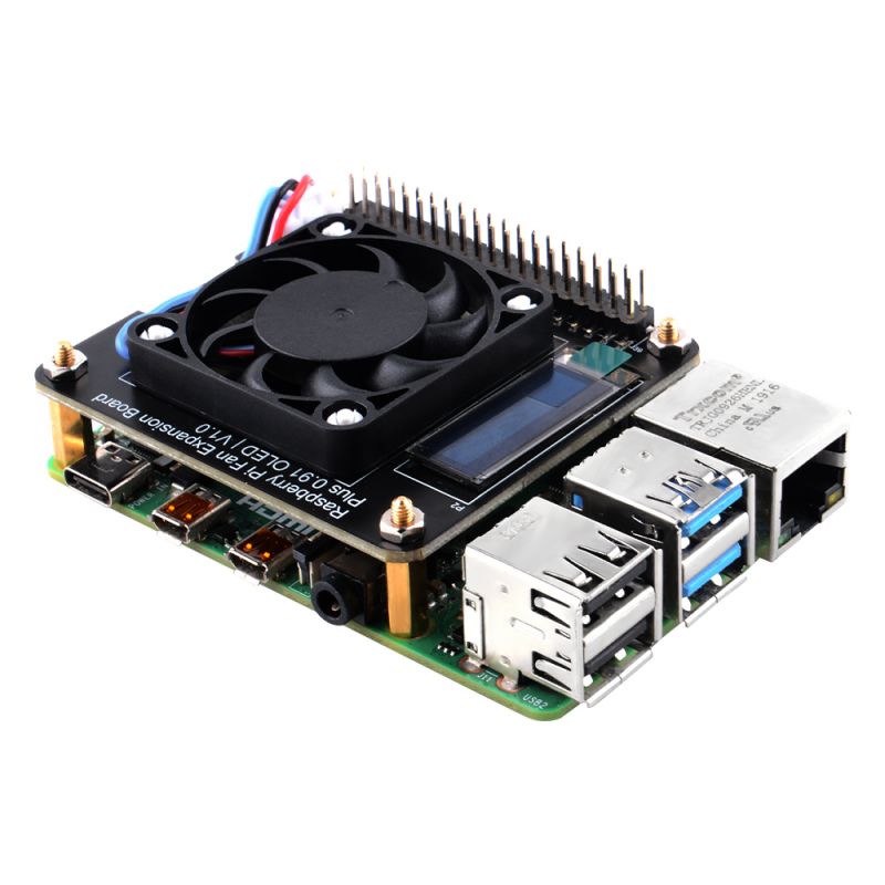
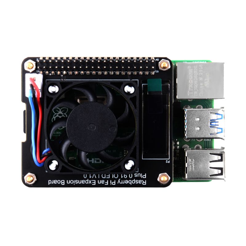
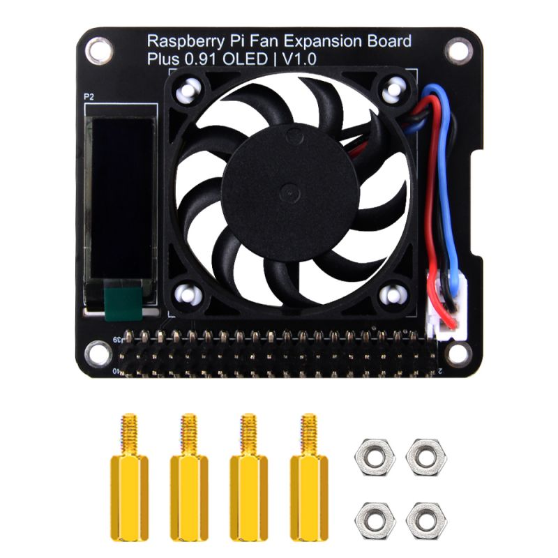
This is a 40pin Raspberry Pi HAT type expansion board, which provides a 0.91 inch display screen connected to the I2C pin. The display information can be customized through the program.
It provides an ultra-thin 4007 silent fan to provide heat dissipation support. There are also 4 customizable LED lights on the back of the board. You can also control the lighting mode of the LED lights through simple programming. The previous HAT board design is used. The 40Pin GPIO can still be easily accessed by users. The new fixing method avoids the risk of short circuit caused by metal parts and provides a good appearance design.
Raspberry Pi 4B does not include in the package.
Features
- Speed Adjustable Fan
- 0.91 Inch OLED Display
- Programmable LED Indicator
- High Performance Heat Dissipation
- GPIO expandable interface
- Hat Style
- Compatible with Raspberry Pi 2B/3B/3B+/4B
- Programmable Background light (Controlled by GPIO)
Gallery
- Product Outlook
- Top view
Package Includes
- 1 x Raspberry Pi Fan Expansion Board Plus 0.91 OLED V1.0
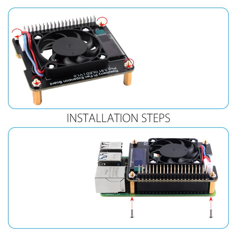
How to assemble
- Connect the Hat board to the GPIO pins of the Raspberry Pi.
- Fix the hat with copper pillars and nuts.
- Fix the hat to Raspberry Pi with screws.
Assemble Steps
How to enable Fan
For Raspberry Pi 5
- Due to compatibility issues with the RPI.GPIO library on Raspberry Pi 5, it can lead to a RuntimeError: Cannot determine SOC peripheral base address, hence the choice to use the gpiozero library for LED control and fan speed control.
- Install python3-gpiozero library
sudo apt update
sudo apt upgrade -y
sudo apt -y install python3-gpiozero
- Create python file to control LEDs, use thonny IDE or other editor, such as vim.tiny and nano editor.
vim.tiny demo_leds_blinking.py
Copy and paste following code:
from gpiozero import LED
from time import sleep


led1 = LED(19)  # BCM Naming system, 19 means GPIO19
led2 = LED(13)
led3 = LED(6)
led4 = LED(5)

interval = 0.2   # delay 0.2 seconds

while True:
    led1.on()
    sleep(interval)
    led2.on()
    sleep(interval)
    led3.on()
    sleep(interval)
    led4.on()
    sleep(interval)
    led1.off()
    sleep(interval)
    led2.off()
    sleep(interval)
    led3.off()
    sleep(interval)
    led4.off()
    sleep(interval)
Save it and execute it by executing following command:
python3 demo_leds_blinking.py
- Fan speed control by using gpiozero library, create a python file named `fan_speed_control.py`, copy and paste following code:
from gpiozero import PWMLED
from time import sleep
import subprocess

# Create a PWMLED object for the fan, assuming it's connected to GPIO 14
fan = PWMLED(14)

# Function to get the CPU temperature
def get_cpu_temperature():
    try:
        # Use the vcgencmd command to get the CPU temperature
        output = subprocess.check_output(['vcgencmd', 'measure_temp']).decode('utf-8')
        # Extract the temperature value
        return float(output.replace('temp=', '').replace("'C\n", ''))
    except Exception as e:
        print(f"Error getting CPU temperature: {e}")
        return None

try:
    while True:
        # Get the CPU temperature
        temp = get_cpu_temperature()
        print(temp)
        if temp is not None:
            # Adjust the fan speed based on the temperature, 45 means CPU temperature is reached to 45 degree, you can modify as your wish.
            if temp > 45:
                fan.value = 1.0  # Fan at full speed
            elif temp < 38:
                fan.value = 0.0  # Fan off
            else:
                fan.value = 0.5  # Fan at half speed

        # Sleep for a short period to avoid high CPU usage
        sleep(0.1)

except KeyboardInterrupt:
    # When Ctrl+C is caught, turn off the fan and exit
    fan.off()
- 0.91 inch OLED display please refer to instruction below, it is the same as it on Raspberry Pi 4B.
For Raspberry Pi 4 and old version OS
- Fit for old Raspberry Pi OS: bullseye
- Open a terminal and typing following command:
sudo raspi-config
- Navigate to `4 Performance Options` -> `P4 Fan` -> `Yes` -> `14` -> `60` -> `OK` -> `OK` -> `Finish` -> `YES`.
- Raspberry Pi will reboot and take effect.
How to control fan speed automatically by CPU temperature
- Create a new python file, name it as "auto_fan.py"
- Copy and paste following code into this file.
 #!/usr/bin/python3

import RPi.GPIO as GPIO
import time
import subprocess

GPIO.setmode(GPIO.BCM)
GPIO.setup(14, GPIO.OUT)
pwm = GPIO.PWM(14,100)

print("\nPress Ctrl+C to quit \n")
dc = 0
pwm.start(dc)

try:
    while True:
        temp = subprocess.getoutput("vcgencmd measure_temp|sed 's/[^0-9.]//g'")
        if round(float(temp)) >= 45:
            dc = 100
            pwm.ChangeDutyCycle(dc)
            print("CPU Temp:",float(temp)," Fan duty cycle:",dc)
            time.sleep(180.0)
        if round(float(temp)) >= 40:
            dc = 85
            pwm.ChangeDutyCycle(dc)
            print("CPU Temp:",float(temp)," Fan duty cycle:",dc)
            time.sleep(120.0)
        else:
            dc = 70
            pwm.ChangeDutyCycle(dc)
            print("CPU Temp:",float(temp)," Fan duty cycle:",dc)
            time.sleep(60.00)

except KeyboardInterrupt:
    pwm.stop()
    GPIO.cleanup()
    print("Ctrl + C pressed -- Ending program")
- Save it and execute it on terminal
python auto_fan.py &
How to check if OLED dislay has been recognized?
- Enable I2C interface
sudo raspi-config
- Navigate to `Interface Options` -> `I2C` -> `Enable` -> `YES`.
- Detect If OLED has been recognized.
i2cdetect -y 1
- OLED default address: `0x3c`
How to lights up OLED Display?
- Enabling The I2C Interface
The I2C interface may not be enabled by default on your SBC. To check if it is enabled:
$ dmesg | grep i2c
[    4.925554] bcm2708_i2c 20804000.i2c: BSC1 Controller at 0x20804000 (irq 79) (baudrate 100000)
[    4.929325] i2c /dev entries driver
or:
$ lsmod | grep i2c
i2c_dev                 5769  0
i2c_bcm2708             4943  0
regmap_i2c              1661  3 snd_soc_pcm512x,snd_soc_wm8804,snd_soc_core
If you have no kernel modules listed and nothing is showing using dmesg then this implies the kernel I2C driver is not loaded.
For Raspberry Pi OS, enable the I2C driver as follows:
- Run sudo raspi-configUse the down arrow to select 5 Interfacing Options
- Arrow down to P5 I2C
- Select yes when it asks you to enable I2C
- Also select yes when it asks about automatically loading the kernel module
- Use the right arrow to select the <Finish> button
- After rebooting re-check that the dmesg | grep i2c command shows whether I2C driver is loaded before proceeding. You can also enable I2C manually if the raspi-config utility is not available.
- Then reboot.
- Next, add your user to the i2c group and install i2c-tools:
$ sudo usermod -a -G i2c pi
$ sudo apt-get install i2c-tools
Logout and in again so that the group membership permissions take effect
Determining Address
Check that the device is communicating properly (if using a rev.1 board, use 0 for the bus, not 1) and determine its address using i2cdetect:
$ i2cdetect -y 1
       0  1  2  3  4  5  6  7  8  9  a  b  c  d  e  f
  00:          -- -- -- -- -- -- -- -- -- -- -- -- --
  10: -- -- -- -- -- -- -- -- -- -- -- -- -- -- -- --
  20: -- -- -- -- -- -- -- -- -- -- -- -- -- -- -- --
  30: -- -- -- -- -- -- -- -- -- -- -- -- 3c -- -- --
  40: -- -- -- -- -- -- -- -- -- -- -- -- -- -- -- --
  50: -- -- -- -- -- -- -- -- -- -- -- -- -- -- -- --
  60: -- -- -- -- -- -- -- -- -- -- -- -- -- -- -- --
  70: -- -- -- -- -- -- -- --
The address for your device will be needed when you initialize the interface. In the example above, the display address is 0x3c. Keep in mind that I2C buses can have more than one device attached. If more than one address is shown when you run i2cdetect, you will need to determine which one is associated with your display. Typically displays will only support a limited set of possible addresses (often just one). Checking the documentation can help determine which device is which.
Software settings
Before installing the library, create a virtual environment for your project using:
$ python3 -m venv ~/luma-env
This creates a virtual environment in the home directory called luma-env and a Python executable at ~/luma-env/bin/python.
- Next, install the latest version of the library in the virtual environment directly with:
$ ~/luma-env/bin/python -m pip install --upgrade luma.oled --break-system-packages
This will normally retrieve all of the dependencies luma.oled requires and install them automatically.
Installing Dependencies
If pip is unable to automatically install its dependencies you will have to add them manually. To resolve the issues you will need to add the appropriate development packages to continue.
If you are using Raspberry Pi OS you should be able to use the following commands to add the required packages:
$ sudo apt-get update
$ sudo apt-get install python3 python3-pip python3-pil libjpeg-dev zlib1g-dev libfreetype6-dev liblcms2-dev libopenjp2-7 -y
Permissions
luma.oled uses hardware interfaces that require permission to access. After you have successfully installed luma.oled you may want to add the user account that your luma.oled program will run as to the groups that grant access to these interfaces.:
$ sudo usermod -a -G gpio,i2c pi
Replace pi with the name of the account you will be using.
Clone repository of luma.examples
git clone https://github.com/rm-hull/luma.examples.git
cd luma.examples
sudo -H pip install -e . --break-system-packages
Run the examples
cd examples/
python3 demo.py --help
NOTE: This 0.91inch OLED display's resolution is 128x32 pixels
How to display system information on OLED display?
- Display basic system information need psutil installed.
sudo -H pip install psutil --break-system-packages
sudo apt -y install python3-dev
According to the examples demo, you can just use "sys_info.py" to display the system information, but the fonts need to be changed so that it can display clearly. check the fonts file in luma.examples/examples/fonts folder, and select one of the fonts to replace the font settings in sys_info.py. For examples: replace 'C&C Red Alart [INET].ttf' in sys_info.py to 'DejaVuSansMono.ttf' find this line:
font_path = str(Path(__file__).resolve().parent.joinpath('fonts', 'C&C Red Alert [INET].ttf'))
replace it to :
font_path = str(Path(__file__).resolve().parent.joinpath('fonts', 'DejaVuSansMono.ttf'))
save it and execute this python script.
python3 sys_info.py
You will see the system information on OLED display.
How to customize your own system infor display?
- According to demo.py of luma.examples, you can create your own system infor and display on OLED display.
For example, I want to display CPU temperature and IP address of Pi, and disk usage of my pi, I create a new python script as following:
#!/usr/bin/env python3
# -*- coding: utf-8 -*-

import time
import subprocess
from demo_opts import get_device
from luma.core.render import canvas


def system_infor(device, draw):
    # First define some constants to allow easy resizing of shapes
    # Move left to right keeping track of the current x position for drawing shapes
    x = 2

    # grap temperature of CPU
    temp =subprocess.getoutput("vcgencmd measure_temp | sed 's/[^0-9.*]//g'")
    # grap capacity of disk usage of /
    disk_usage = subprocess.getoutput("df -Th / | awk '{print $6}' | tail -n1")
    # grap memory infor
    free_mem = subprocess.getoutput("free -g |grep Mem | awk '{print $4}'")
    # Network Status
    IP = subprocess.getoutput("hostname -I | awk '{print $1}'")
    draw.rectangle((x, 0, 128, 32), fill="black")
    # draw.text((device.width - padding - w, top + 4), temp, fill="cyan")
    # draw.text((device.width - padding - w, top + 16), 'haha', fill="purple")
    draw.text((x, 0),'CPU TEMP:', fill="white")
    draw.text((56, 0), temp, fill="white")
    draw.text((82, 0), '°C', fill="white")
    draw.text((x, 8),'IP ADDR:', fill="white")
    draw.text((52, 8), IP, fill="white")
    draw.text((x, 16),'SD USAGE:', fill="white")
    draw.text((58, 16), disk_usage, fill="white")
    draw.text((78, 16), 'MEM:', fill="white")
    draw.text((100, 16), free_mem, fill="white")
    draw.text((104, 16), ' GB', fill="white")

    # Draw a rectangle of the same size of screen
    draw.rectangle(device.bounding_box, outline="white")


device = get_device()

while True:
    with canvas(device) as draw:
        system_infor(device, draw)
        time.sleep(5)
- Save it and execute it in a terminal:
python3 system_info.py --width 128 --height 32
- You will see:
How can these executable Python scripts be turned into systemd-style background services?
There are three services you can create on your Raspberry Pi OS.
- 1. Service of Fan control by CPU temperature
- 2. Service of LEDs blinking patterm.
- 3. Service of OLED display control
At the first, you need to create all of the demo code in your system. Following is the demo code:
- Fan controlled by CPU's temperature, create a python script file named it autofan.py and place it to /home/pi/fan_test/ folder:
#!/usr/bin/python3

import RPi.GPIO as GPIO
import time
import subprocess

GPIO.setmode(GPIO.BCM)
GPIO.setup(14, GPIO.OUT)

pwm = GPIO.PWM(14, 100)

# print("\nPress Ctrl+C to quit \n")

dc = 0

pwm.start(dc)

try:
    while True:
        temp = subprocess.getoutput("vcgencmd measure_temp|sed 's/[^0-9.]//g'")
        if round(float(temp)) >= 45:
            dc = 100
            pwm.ChangeDutyCycle(dc)
            time.sleep(180)

        if round(float(temp)) >= 40:
            dc = 85
            pwm.ChangeDutyCycle(dc)
            time.sleep(120)
        else:
            dc = 70
            pwm.ChangeDutyCycle(dc)
            time.sleep(60)

except KeyboardInterrupt:
    pwm.stop()
    GPIO.cleanup()
- Save it and make sure it can execute in your terminal.
- Next step is to create a systemd style file in location: '/etc/systemd/system/'
sudo vim.tiny /etc/systemd/system/52piFan.servicce
And filling following lines:
[Unit]
Description=52Pi Pi fan expansion board Fan control service v1.0
After=multi-user.target

[Service]
Type=simple
RemainAfterExit=true
ExecStart=/usr/bin/python3 /home/pi/fan_test/autofan.py

[Install]
WantedBy=multi-user.target
- Save it and reload the daemon and start service .
sudo systemctl daemon-reload
sudo systemctl enable 52piFan.service
sudo systemctl start 52piFan.service
And use the same method to create another services: For the LEDs, for examples, create a python file called: led_blinking.py in /home/pi location as following demo code.
import RPi.GPIO as GPIO
import time


LED1 = 19 # BCM naming system
LED2 = 13
LED3 = 6
LED4 = 5
interval = 0.2

GPIO.setmode(GPIO.BCM)
GPIO.setwarnings(False)
GPIO.setup(LED1, GPIO.OUT)
GPIO.setup(LED2, GPIO.OUT)
GPIO.setup(LED3, GPIO.OUT)
GPIO.setup(LED4, GPIO.OUT)

while True:
    for i in range(10):
        GPIO.output(LED1, GPIO.HIGH)
        time.sleep(interval)
        GPIO.output(LED2, GPIO.HIGH)
        time.sleep(interval)
        GPIO.output(LED3, GPIO.HIGH)
        time.sleep(interval)
        GPIO.output(LED4, GPIO.HIGH)
        time.sleep(interval)

    time.sleep(1)

    for i in range(10):
        GPIO.output(LED1, GPIO.LOW)
        time.sleep(interval)
        GPIO.output(LED2, GPIO.LOW)
        time.sleep(interval)
        GPIO.output(LED3, GPIO.LOW)
        time.sleep(interval)
        GPIO.output(LED4, GPIO.LOW)
        time.sleep(interval)

GPIO.cleanup()
and then create systemd file in /etc/systemd/system/lights.service
sudo vim.tiny /etc/systemd/system/lights.service
and filling with following lines:
[Unit]
Description=52Pi Raspberry Pi Fan Extansion board Plus 0.91 OLED v1.0
After=multi-user.target

[Service]
Type=simple
RemainAfterExit=true
ExecStart=/usr/bin/python3 /home/pi/led_blinking.py

[Install]
WantedBy=multi-user.target
- save it and reload daemon as previous steps
sudo systemctl daemon-reload
sudo systemctl enable lights.service
sudo systemctl start lights.service
- For the OLED display is the same.
For example, you have already create virtual env in your local system, the path of the venv location will be at /home/pi/luma-env/luma.examples/examples/, and I have create my own customized script named "system_infor.py". so the systemd file be like:
- Create a systemd file named: oled.service
sudo vim.tiny /etc/systemd/system/oled.service
- Filling the file with following lines:
[Unit]
Description=52Pi Pi Fan Expansion board plus OLED display service v1.0
After=multi-user.target

[Service]
Type=simple
RemainAfterExit=true
ExecStart=/usr/bin/python3 /home/pi/luma-env/luma.examples/examples/system_infor.py --width 128 --height 32

[Install]
WantedBy=multi-user.target
- Save it and reload the daemon
sudo systemctl daemon-reload
sudo systemctl enable oled.service
sudo systemctl start oled.service
- After that, even if you reboot your Raspberry Pi, it will bring up automatically.
Easy Install
- Download the repository from github:
git clone https://github.com/geeekpi/RPiFEBP.git
cd RPiFEBP/
./install.sh
More information please refer to README.md file.
How to Setup LED indicator
- LED indicators Pin out
There are 4 LED under the PCB board.
- LED1 - nearby the GPIO pins and fan on left corner, connect to `GPIO 24` (BCM 19)
- LED2 - under LED1, connect to `GPIO 23` (BCM 13)
- LED3 - on the right of LED2, connect to `GPIO 22` (BCM 6)
- LED4 - on the top of LED3, connect to `GPIO 21` (BCM 5)
- Create python script as following:
import RPi.GPIO as GPIO
import time

LED1 = 19
LED2 = 13
LED3 = 6
LED4 = 5

GPIO.setmode(GPIO.BCM)
GPIO.setup(LED1,GPIO.OUT)
GPIO.setup(LED2,GPIO.OUT)
GPIO.setup(LED3,GPIO.OUT)
GPIO.setup(LED4,GPIO.OUT)

while True:
    for i in range(10):
        GPIO.output(LED1, GPIO.HIGH)
        time.sleep(0.5)
        GPIO.output(LED2, GPIO.HIGH)
        time.sleep(0.5)
        GPIO.output(LED3, GPIO.HIGH)
        time.sleep(0.5)
         GPIO.output(LED4, GPIO.HIGH)
        time.sleep(0.5)
    time.sleep(1)
        for i in range(10):
            GPIO.output(LED1, GPIO.LOW)
            time.sleep(0.5)
            GPIO.output(LED2, GPIO.LOW)
            time.sleep(0.5)
            GPIO.output(LED3, GPIO.LOW)
            time.sleep(0.5)
            GPIO.output(LED4, GPIO.LOW)
            time.sleep(0.5)
 * Save it and execute it.
<pre>
python3 led_blink.py
- Reinstall wiringPi library.(Deprecated)
sudo apt -y purge wiringpi
hash -r
cd /tmp
wget https://project-downloads.drogon.net/wiringpi-latest.deb
sudo dpkg -i wiringpi-latest.deb
gpio readall
- Demo code in shell:
for i in `seq 21 24`
 do
    gpio mode $i out
 done

while true
do
  for i in `seq 21 24`
  do
	gpio write $i 1
  	sleep 0.01
  	gpio write $i 0
  done
done
Control LED on the bottom of expansion board by using RPi.GPIO library.
- Demo code in Python:
import RPi.GPIO as GPIO
import time


# BCM Number of LED indicators
leds = [5, 6, 13, 19]

GPIO.setmode(GPIO.BCM)
GPIO.setwarnings(False)

for i in range(len(leds)):
    GPIO.setup(leds[i], GPIO.OUT)


try:
    while True:
	for led in leds:
       	    GPIO.output(led, GPIO.HIGH)
	    time.sleep(0.01)
            GPIO.output(led, GPIO.LOW)
except KeyboardInterrupt:
    GPIO.cleanup()
    print("BYE")
Keywords
- Raspberry Pi Fan Expansion Board Plus 0.91 OLED V1.0, Fan expansion board, oled 0.91, raspberry Pi 4B, heat dissipation, hat board for raspberry Pi 4B
