KZ-0058: Difference between revisions
(Created page with "==Arduino UNO R3 Smart Car Kit== right|320px ==Description== This kit provides a comprehensive set of hardware components aimed at facilitating Arduino-based projects. It includes an Arduino UNO R3 development board as the central control unit, along with peripherals such as an ultrasonic sensor for distance measurement, an infrared line tracking module for path following, a DRV8833 driver board for motor control, and a HAT board with LED indicato...") |
|||
| Line 61: | Line 61: | ||
[[ File:Kz-0058 install 21.jpg|left|800px]] | [[ File:Kz-0058 install 21.jpg|left|800px]] | ||
<br style="clear:both;"> | <br style="clear:both;"> | ||
When installing the DRV8833 motor driver board, please pay attention to the installation direction. There is a silk screen on the expansion board that clearly shows the corresponding direction. | [[ File:Kz-0058 install 18.jpg|left|800px]] | ||
<br style="clear:both;"> | |||
* Details of DRV8833 Driver | |||
[[File:Drv8833 Zoomin.png|left|800px]] | |||
<br style="clear:both;"> | |||
[[File:Drv8833 Zoomin2.png|left|800px]] | |||
<br style="clear:both;"> | |||
When installing the DRV8833 motor driver board, please pay attention to the installation direction. There is a silk screen on the expansion board that clearly shows the corresponding direction. <br> | |||
<font color=red>Please note that installation in the wrong direction may damage the driver board.</font><br> | <font color=red>Please note that installation in the wrong direction may damage the driver board.</font><br> | ||
[[ File: | |||
===Step 3. Install line tracking module | |||
Fix the double-through copper pillar to line tracking module with flat head M2.5 screw according to following figure: | |||
[[File:Line tracking module installation.png|left|800px]] | |||
<br style="clear:both;"> | <br style="clear:both;"> | ||
[[ File:Kz-0058 install 17.jpg|left|800px]] | [[ File:Kz-0058 install 17.jpg|left|800px]] | ||
<br style="clear:both;"> | <br style="clear:both;"> | ||
And then fix it to the chassis on following position, make sure it aligned straight to forward. | |||
[[ File:Kz-0058 install 16.jpg|left|800px]] | [[ File:Kz-0058 install 16.jpg|left|800px]] | ||
<br style="clear:both;> | |||
* Installation details | |||
[[File:Line tracking module installation2.png|left|800px]] | |||
<br style="clear:both;"> | <br style="clear:both;"> | ||
[[File:Line tracking module installation3.png|left|800px]] | |||
<br style="clear:both;"> | |||
[[File:Line tracking module installation4.png|left|800px]] | |||
<br style="clear:both;"> | |||
There are two holes for adjusting the potentiometer on the line tracking module. | |||
Then find 6 male and female DuPont wires, connect the DuPont wires to the pins of the line tracking module, and connect them to VCC, GND, and AO respectively. Then pass the wire through the center hole of the base plate as following figure: | |||
[[ File:Kz-0058 install 15.jpg|left|800px]] | [[ File:Kz-0058 install 15.jpg|left|800px]] | ||
<br style="clear:both;"> | <br style="clear:both;"> | ||
===Step 4: Fixed host computer module=== | |||
Fix the host computer to the base plate and find the battery box, Bluetooth module and ultrasonic module for spare use. | |||
[[ File:Kz-0058 install 14.jpg|left|800px]] | [[ File:Kz-0058 install 14.jpg|left|800px]] | ||
<br style="clear:both;"> | <br style="clear:both;"> | ||
[[ File:Kz-0058 install | ===Step 5:Install the battery box === | ||
Use two screws and two nuts to fix the battery box to the bottom plate. Please keep the DC interface of the battery box close to the DC port of arduino UNO R3. | |||
[[ File:Kz-0058 install 11.jpg|left|800px]] | |||
<br style="clear:both;"> | <br style="clear:both;"> | ||
===Step 6: Install the expansion board=== | |||
Insert the expansion board into Arduino UNO R3 and secure it with M2.5 flat head screws. | |||
[[ File:Kz-0058 install 12.jpg|left|800px]] | [[ File:Kz-0058 install 12.jpg|left|800px]] | ||
<br style="clear:both;"> | <br style="clear:both;"> | ||
[[ File:Kz-0058 install | [[ File:Kz-0058 install 13.jpg|left|800px]] | ||
<br style="clear:both;"> | <br style="clear:both;"> | ||
[[ File:Kz-0058 install 10.jpg|left|800px]] | [[ File:Kz-0058 install 10.jpg|left|800px]] | ||
<br style="clear:both;"> | <br style="clear:both;"> | ||
===Step 7: Connect the motor cable to expansion board.=== | |||
Please pay attention to the order of the motor interfaces, carefully observe the motor power pins, the red and black cables, the left and right sides are opposite. If the installation is wrong, it may cause the motor to rotate reversely during program debugging. If the installation is incorrect, you can remove the motor and reinstall it. | |||
[[File:Motor installation 01.png|left|800px]] | |||
<br style="clear:both;"> | |||
[[ File:Kz-0058 install 9.jpg|left|800px]] | [[ File:Kz-0058 install 9.jpg|left|800px]] | ||
<br style="clear:both;"> | <br style="clear:both;"> | ||
| Line 100: | Line 133: | ||
[[ File:Kz-0058 install 1.jpg|left|800px]] | [[ File:Kz-0058 install 1.jpg|left|800px]] | ||
<br style="clear:both;"> | <br style="clear:both;"> | ||
===Step 4.=== | ===Step 4.=== | ||
===Step 5. === | ===Step 5. === | ||
Revision as of 14:10, 16 May 2024
Arduino UNO R3 Smart Car Kit
Description
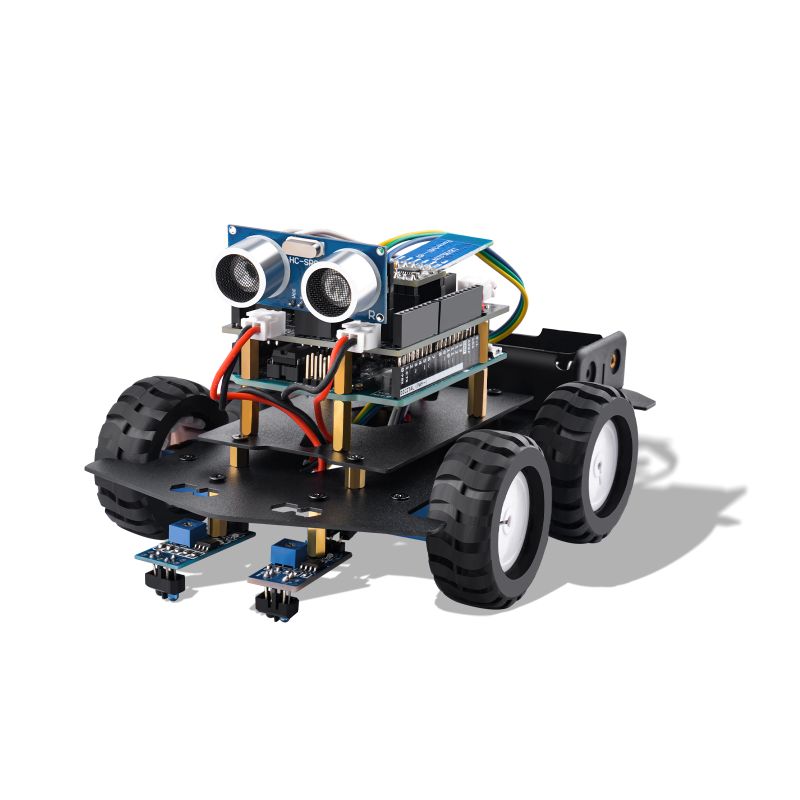
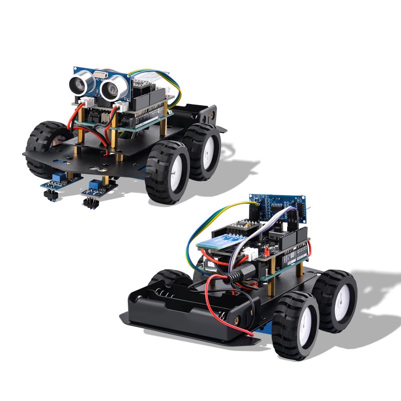
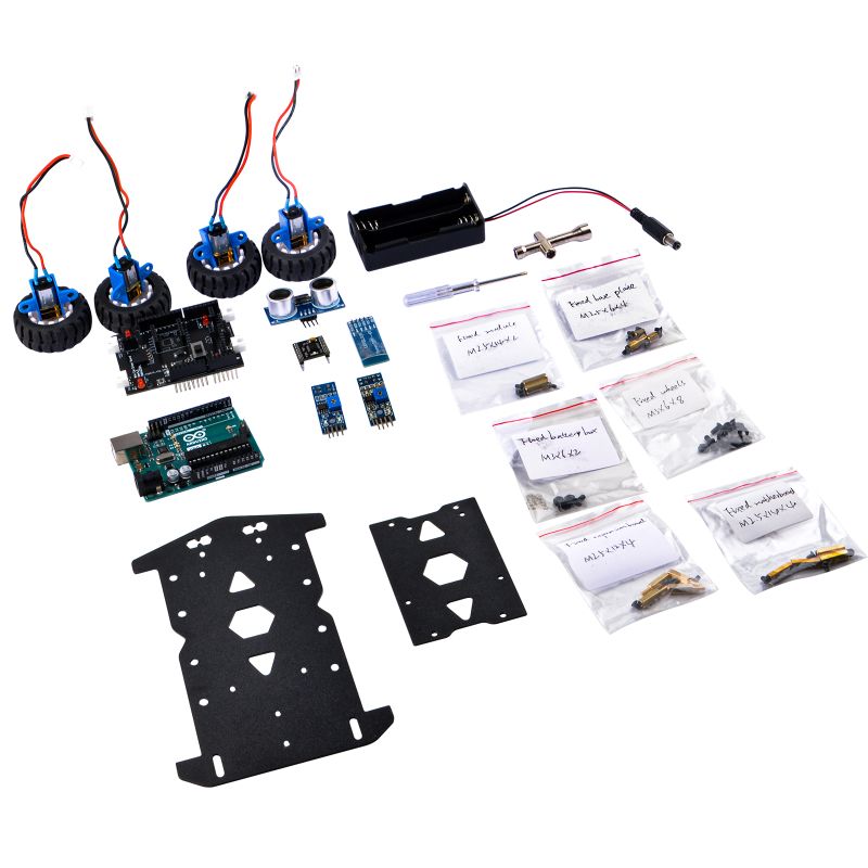
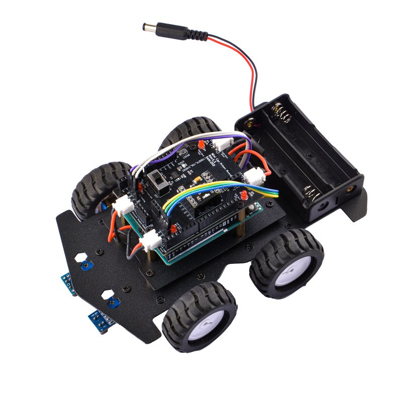
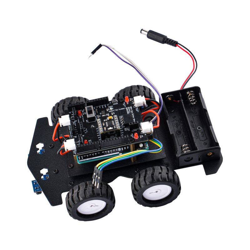
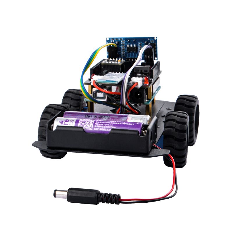
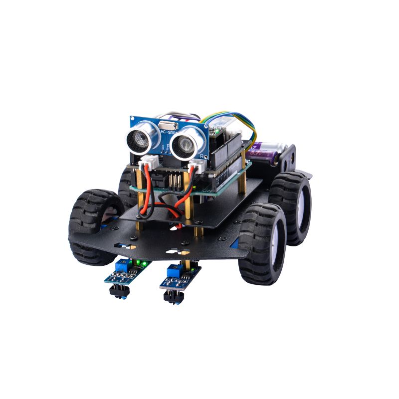
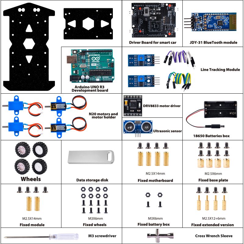
This kit provides a comprehensive set of hardware components aimed at facilitating Arduino-based projects. It includes an Arduino UNO R3 development board as the central control unit, along with peripherals such as an ultrasonic sensor for distance measurement, an infrared line tracking module for path following, a DRV8833 driver board for motor control, and a HAT board with LED indicators, power management switches, and motor interfaces. Additionally, it features N20 reduction motors, a JDY-31 Bluetooth module for wireless communication, and an Android smartphone app for remote control and monitoring. This kit enables users to easily develop projects ranging from obstacle-avoiding robots to smart vehicles, providing a versatile platform for innovation and experimentation.
Features
- Arduino UNO R3 Development Board: Serving as the core control unit, it boasts powerful processing capabilities and abundant expansion interfaces, enabling the development and realization of various projects.
- Ultrasonic Sensor: Used for distance measurement, it enables intelligent obstacle avoidance, enhancing the stability and reliability of projects in complex environments.
- Infrared Line Tracking Module: Capable of intelligent path following, it equips projects with automatic navigation and positioning capabilities.
- DRV8833 Driver Board: Providing robust motor driving capabilities, it supports the control of DC motors, enabling projects to perform motion and action execution.
- HAT Board: Specifically designed for the Arduino UNO R3, it offers rich interfaces and functions, including LED indicators, power management switches, and fail-safe motor interfaces, making hardware connections more convenient and reliable.
- N20 Reduction Motors: Utilizing N20 reduction motors, they offer stability and efficiency, suitable for various mechanical motion control scenarios.
- JDY-31 Bluetooth Module: Through Bluetooth connection, it achieves wireless communication and control with Android smartphones, granting projects remote control and monitoring capabilities.
- Android Smartphone App: Providing a user-friendly mobile application, it allows users to easily control and monitor various functions of the kit, enhancing user experience and interactivity.
Documentations Download
- GitHub: [ https://github.com/geeekpi/Arduino_UNO_R3_Smart_Car_Kit ]
- Software: [ https://www.arduino.cc/en/software ]
Gallery
- Product Outlook
How to assemble it?
- Please assembit it according following figures.
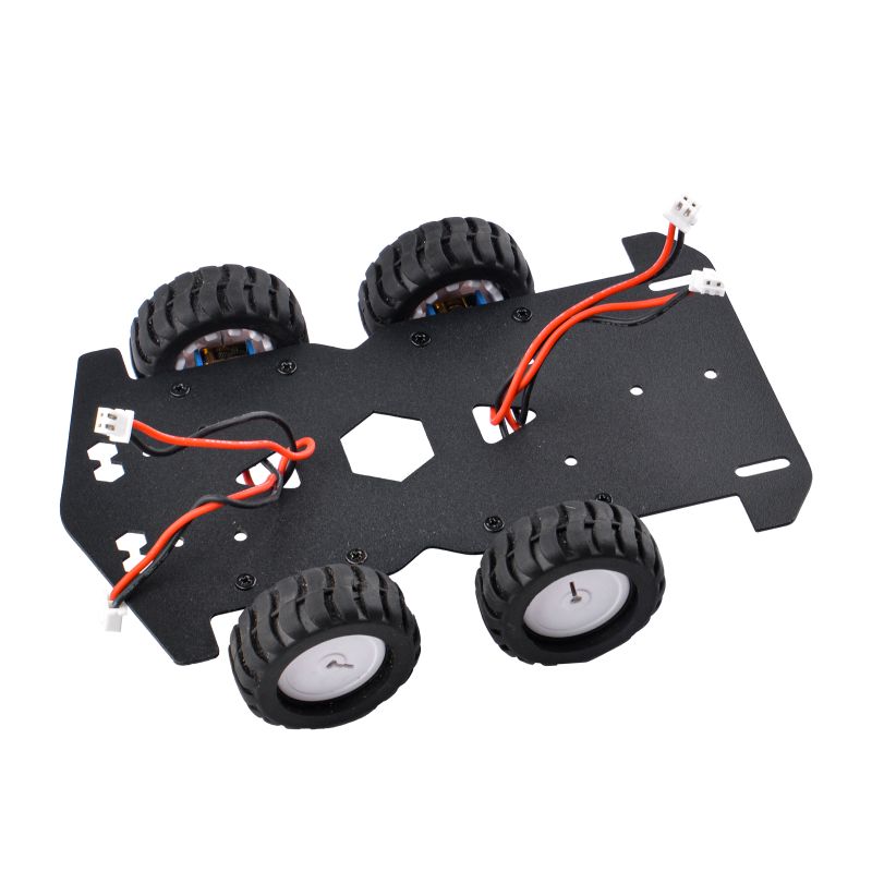
Step 1.Install the trolley chassis
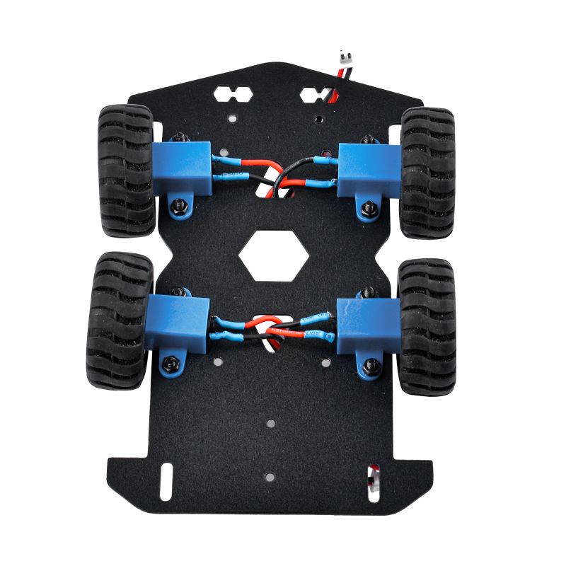
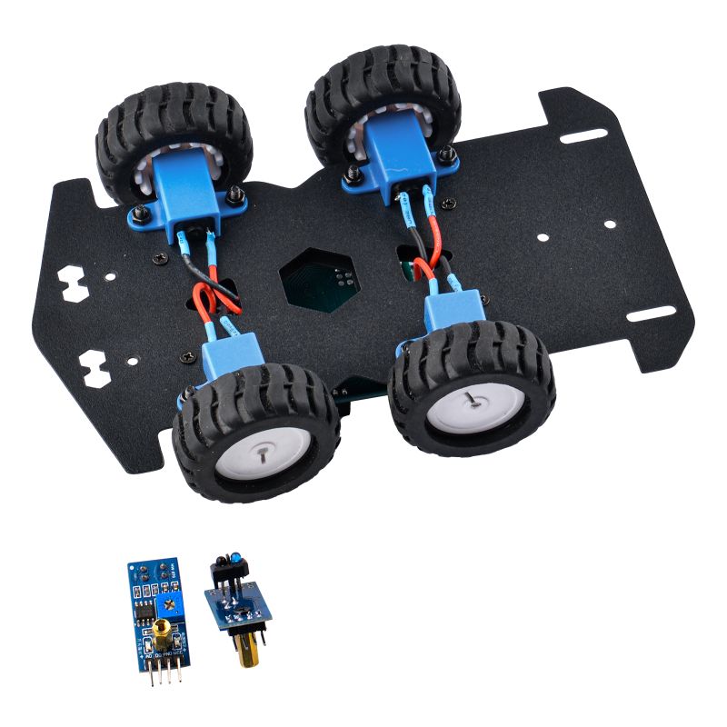
To install the N20 motors, begin by attaching each motor to its respective motor holder using M3 screws and nuts, ensuring they are securely fastened. Then, solder the cables onto each motor, ensuring proper polarity alignment. Next, affix the rubber wheels onto the motor shafts, ensuring they are snugly fitted. Once all components are assembled, place the motors in the desired configuration, ensuring proper alignment and spacing between wheels. Finally, connect the motors to the appropriate power source and test the functionality to ensure smooth operation.
The reason for installing the front wheels with an outer eight and the rear wheels with an inner eight configurations may be to enhance maneuverability and stability. Placing the front wheels on outer brackets allows for increased agility and responsiveness during steering, making it easier to turn. On the other hand, positioning the rear wheels on inner brackets contributes to improved stability and traction, particularly during high-speed driving or cornering, reducing the risk of slipping or skidding and providing better control over the vehicle's movement.
Camber angle is the angle of the wheel relative to the vertical axis when viewed from the front or rear of the vehicle. It is the tilt of the wheel either towards the vehicle (negative camber) or away from it (positive camber).
Negative camber occurs when the top of the wheel leans inward towards the vehicle. This setup is often used in performance vehicles or racing cars as it can improve cornering grip and stability by keeping more of the tire's contact patch on the road during hard cornering. However, excessive negative camber can lead to uneven tire wear, particularly on the inside edge of the tires.
Positive camber occurs when the top of the wheel leans outward away from the vehicle. It is less common in modern vehicles and is usually associated with older vehicles or certain specialized applications. Positive camber can provide better stability in certain situations, such as when carrying heavy loads, but excessive positive camber can lead to reduced grip and uneven tire wear on the outer edges of the tires.
The appropriate camber angle for a vehicle depends on factors such as the vehicle's suspension geometry, intended use, and driver preferences. It is often adjusted during wheel alignment to optimize tire wear, handling, and stability.
Fix the motor holder with M3 screws and nuts, and put the cable through the holes on the metal plate.
Step 2. Install the host computer part
NOTE:
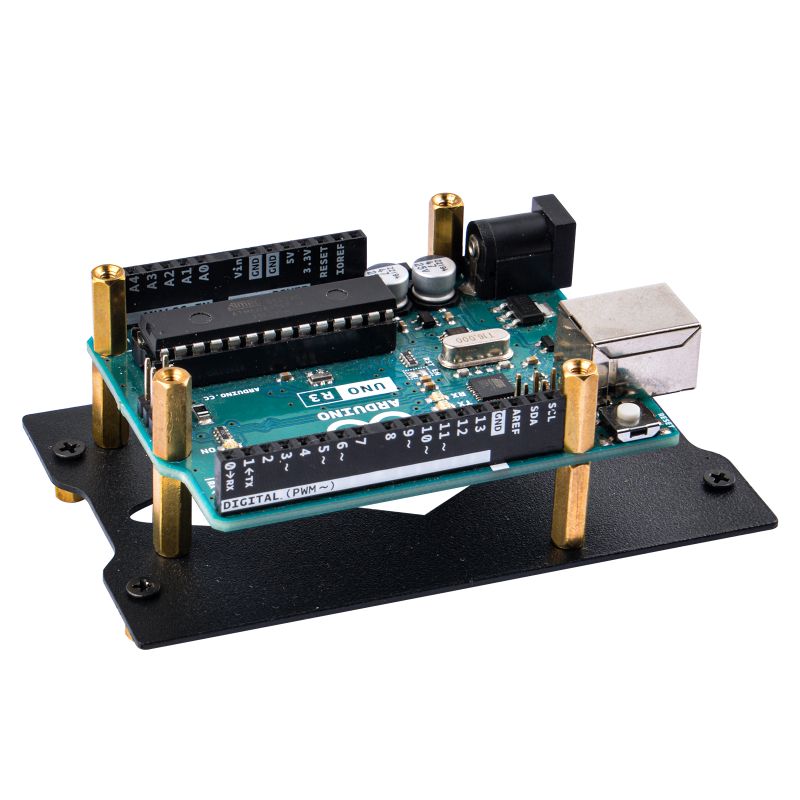
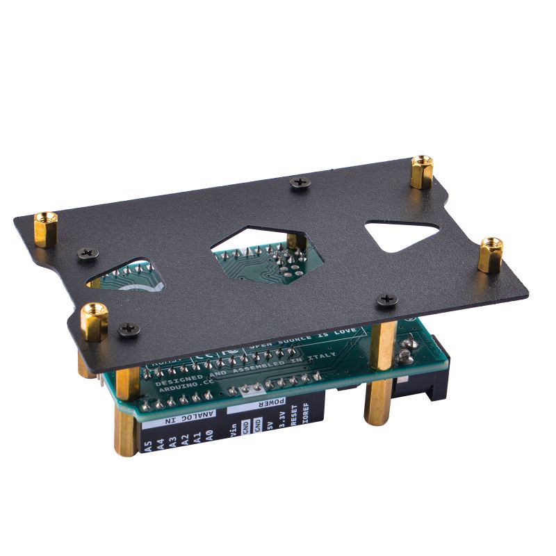
Insert the Arduino UNO R3 and the car's expansion board according to the pin alignment. Before inserting, please carefully observe the installation method of the copper pillars.
Step 3.Fix the small copper pillar to the metal panel with M2.5 flat head screws.
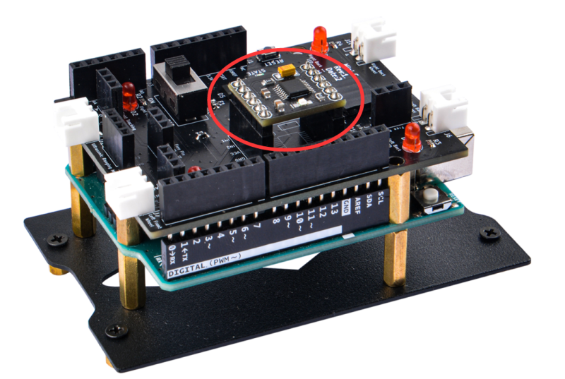
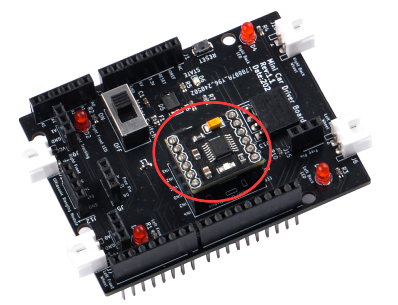
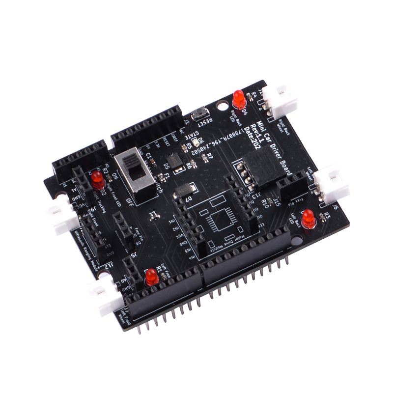
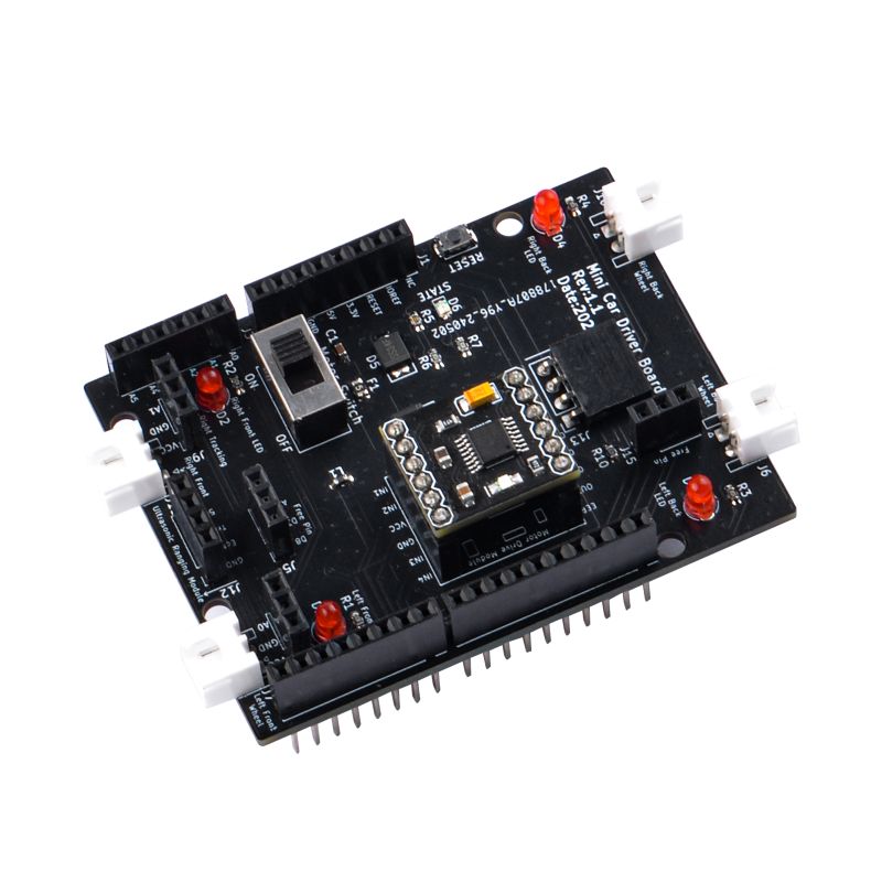
- Details of DRV8833 Driver
When installing the DRV8833 motor driver board, please pay attention to the installation direction. There is a silk screen on the expansion board that clearly shows the corresponding direction.
Please note that installation in the wrong direction may damage the driver board.
===Step 3. Install line tracking module Fix the double-through copper pillar to line tracking module with flat head M2.5 screw according to following figure:
And then fix it to the chassis on following position, make sure it aligned straight to forward.
- Installation details
There are two holes for adjusting the potentiometer on the line tracking module.
Then find 6 male and female DuPont wires, connect the DuPont wires to the pins of the line tracking module, and connect them to VCC, GND, and AO respectively. Then pass the wire through the center hole of the base plate as following figure:
Step 4: Fixed host computer module
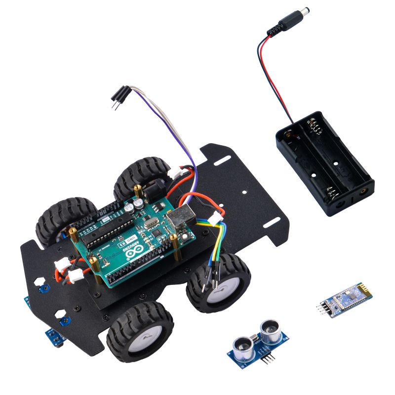
Fix the host computer to the base plate and find the battery box, Bluetooth module and ultrasonic module for spare use.
Step 5:Install the battery box
Use two screws and two nuts to fix the battery box to the bottom plate. Please keep the DC interface of the battery box close to the DC port of arduino UNO R3.
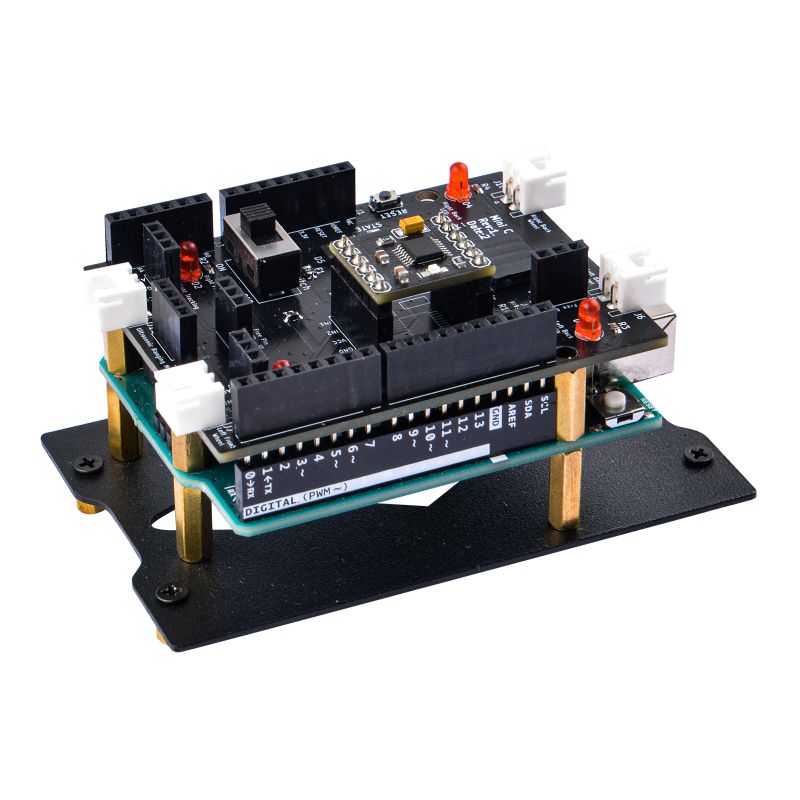
Step 6: Install the expansion board
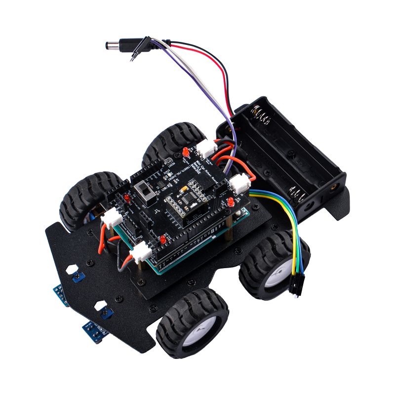
Insert the expansion board into Arduino UNO R3 and secure it with M2.5 flat head screws.
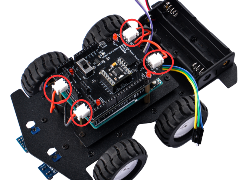
Step 7: Connect the motor cable to expansion board.
Please pay attention to the order of the motor interfaces, carefully observe the motor power pins, the red and black cables, the left and right sides are opposite. If the installation is wrong, it may cause the motor to rotate reversely during program debugging. If the installation is incorrect, you can remove the motor and reinstall it.
Step 4.
Step 5.
Step 6.
Step 7.
Step 8.
Step 9.
Step 10.
Step 11.
Package Includes

