EP-0105: Difference between revisions
Jump to navigation
Jump to search
| Line 278: | Line 278: | ||
list_real = [] | list_real = [] | ||
list_cmp = [170,85,165,90] | # User Define the data information | ||
list_cmp = [170,85,165,90] | |||
list_real.append(bus.read_byte_data(0x16,0x11)) | list_real.append(bus.read_byte_data(0x16,0x11)) | ||
list_real.append(bus.read_byte_data(0x16,0x12)) | list_real.append(bus.read_byte_data(0x16,0x12)) | ||
Revision as of 21:35, 21 June 2019
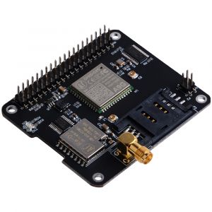
IoT Node(A)

Descriptions
Iot Node(A) is one of Docker Pi series module.
It contains GSM module, GPS module and Lora module onboard.
Features
- Easy to Use
- Support I2C protocol communication
- High Quality A9G module
- High Quality Lora module
- Low Power Consumption
- Long Range Transmission
- Working temperature: 0°C ~ 65°C
- LORA antenna gain: 2db
- GPS antenna gain: 1.5db
- GSM antenna gain: 2db
- Supply voltage: 5V + 3V dual power supply
- Pure I2C communication, does not occupy other IO, leads to the GPIO pin.
Specifications
GPRS section
- 1. Low power consumption, standby sleep current <1mA
- 2. Support GSM/GPRS four frequency bands, including 850, 900, 1800, 1900MHZ;
- 3. GPRS Class 10;
- 4. Support GPRS data service, maximum data rate, download 85.6Kbps, upload 42.8Kbps;
- 5. Support standard GSM07.07, 07.05 AT commands, and access the serial port through I2C interface conversion.
- 6. AT commands support standard AT and TCP/IP command ports
GPS section
- 1. Support BDS/GPS joint positioning
- 2. Support A-GPS, A-BDS
- 3. Support standard SIM card
LORA section
- 1. City working conditions: transmission distance of 500 meters (RF parameters: 0x50)
In all cases: the minimum guaranteed 300 meters transmission.
- 2. Support FSK, GFSK, MSK, GMSK, LoRaTM and OOK modulation methods
- 3. Ultra-high receiver sensitivity as low as -141 dBm
- 4. Support preamble detection
- 5. Packet engine with CRC, up to 256 bytes
- 6. LORA transceiver indicator
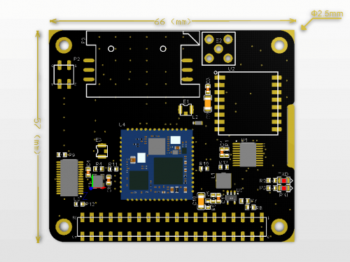
Mechanical Drawings

Gallery
|
 |
 |
 |
 |
 |
Documentations
- A9G Module Spicification: File:A9g product specification.pdf
- A9G Module AT Command Manual: File:A9G AT COMMAND manual.pdf
- A9G gprs series module at instruction set v1.0 File:A9G gprs series module at instruction set v1.0.pdf
- GPRS C SDK: File:GPRS C SDK-master.zip
Technical Details
A9G module
- Serial port : A9G module offers two serial port.
| Serial Port | Module name |
|---|---|
| /dev/ttySC0 | GPRS |
| /dev/ttySC1 | GPS |
Register Map
- Lora instruction section:
1) The 0x22 register is used to configure the parameters of the Lara.
After the register is written, it needs to write 1 at the corresponding position of the 0×23 register to make the setting take effect.
2) The first 16 bytes of the module are used to store the data specific address 0x01-0x10 that the user wants to send, and the 16 byte space from 0x11-0x21 is used to store the data received by the user.
| Register Address | 0x22 | |||||||
|---|---|---|---|---|---|---|---|---|
| Name | - | SpreadingFactor | SignalBandwidth | ErrorCoding | ||||
| Default Value | 0 | 1 | 0 | 1 | 1 | 0 | 1 | 1 |
| Description | Reserved | Band range 7-12 | Spread spectrum bandwidth 6-9 | Effective data ratio 1-4 | ||||
| Register Address | 0x23 | |||||||
|---|---|---|---|---|---|---|---|---|
| Default Value | 0 | 0 | 0 | 0 | 0 | 0 | 0 | 0 |
| Description | Write the setting parameters in the 0x22 address to Lora | Reset A9G module | Reserved | Reserved | Reserved | Reserved | Receive data set | Send user data |
| Register address | Function |
|---|---|
| 0x23 | register write reference |
| 0X01 | Send user data |
| 0X02 | Receive data set |
| 0X40 | Reset A9G |
| 0X80 | Set the Lora register |
How to use
How to assemble
- Mount the Iot Node(A) board to Raspberry Pi
- Hookup GPS antana and Lora antana to IPX port.
- Screws the GPRS antana on the SMA port.
 |
 |
How to configure
- FLash TF card with the latest raspbian image.
- Replace /boot/overlays/sc16is752-i2c.dtbo file with this file: File:Sc16is752-i2c.zip
NOTE: Please unzip it after donwloading.
- Modify /boot/config.txt file and add following parameter:
dtoverlay=sc16is752-i2c
- Reboot Raspberry Pi
- Login Raspberry pi and make sure connect to internet, open a terminal and typing:
sudo apt-get update
sudo apt-get -y install gpsd gpsd-clients python-gps
- Modify "/etc/default/gpsd" file and add following parameters:
DEVICES="/dev/ttySC1"
GPSD_OPTIONS='-F /var/run/gpsd.sock'
How to use GPS module
- NOTE: GPS module is OUTDOOR module, please test it outside.
- Open a terminal and typing:
sudo systemctl restart gpsd.socket
sudo cgps -s
- Python Programming:
#!/usr/bin/env python3
import serial
import smbus
from gps import *
import os

# Restart gpsd service.
os.system("sudo systemctl restart gpsd.socket")
# Open serial port
ser = serial.Serial('/dev/ttySC0', 115200)

if ser.isOpen == False:
    ser.open()
try:
    print("Turn on GPS switch")
    ser.write(str.encode("AT+GPS=1\r"))
    time.sleep(1)
    os.system("sudo cgps -s")
except KeyboardInterrupt:
    ser.flushInput()
    ser.close()
- Save it and execute it:
chmod +x mygps.py
./mygps.py
How to use GPRS module
- Insert the SIM card(It may need you purchase from ISP vendor).
- Create a file named gprs.py
- Paste follow code into the file and save it.
#!/usr/bin/env python3
import serial
import time
import smbus
import operator
import os

print("Waiting for initializing...")
time.sleep(2)

bus = smbus.SMBus(1)

ser = serial.Serial('/dev/ttySC0', 115200)

if ser.isOpen == False:
    ser.open()
try:
    print('-'*60)
    print("Initializing A9G GPRS module.")
    print("GSM connecting...")
    time.sleep(3)
    i = 0
    while True:
        ser.write(str.encode("AT+CCID\r"))
        size = ser.inWaiting()
        if size != 0:
            ticks = time.time()
            response = ser.read(size)
            ccid = str(response,encoding="utf-8")
            if(ccid.find("89860") != -1):
                ccid_result_tmp1 = ccid.splitlines()
                ccid_result = ccid_result_tmp1[2].split(": ")
                if len(ccid_result) > 1:
                    print("SIM card OK, Network access testing is normal. Please check whether the card serial number is the same. number:" + ccid_result[1]);
                    time.sleep(3)
                    print('-'*60)
            else:
                i = i + 1
                print("Waiting network, If the time is too long, it may be a malfunction, or the SIM card is bad.:" + str(i))
                ser.flushInput()
                time.sleep(1)
except KeyboardInterrupt:
    ser.close()
- Add executable rights and run:
chmod +x gprs.py
./gprs.py
How to use Lora module
- Create a file named: lora_test.py
- Copy and paste following code into the file and save it.
#!/usr/bin/env python3
import serial
import time
import smbus
import operator
from gps import *
import os

print("Wait for the microcontroller to complete initialization...")
bus.write_byte_data(0x16,0x23,0x40)
time.sleep(2)

bus = smbus.SMBus(1)

ser = serial.Serial('/dev/ttySC0', 115200)

if ser.isOpen == False:
    ser.open()
try:
    print('-'*60)
    print("Initialize A9G, it takes some time while keeping the LORA transmitter open, testing the LORA module.")
    bus.write_byte_data(0x16,0x23,0x40)

    print("LORA test preparation in progress...")

    bus.write_byte_data(0x16,0x11,0x00)
    bus.write_byte_data(0x16,0x12,0x00)
    bus.write_byte_data(0x16,0x13,0x00)
    bus.write_byte_data(0x16,0x14,0x00)

    print("Receiving data check...")

    time.sleep(2)

    list_real = []
    # User Define the data information
    list_cmp = [170,85,165,90]
    list_real.append(bus.read_byte_data(0x16,0x11))
    list_real.append(bus.read_byte_data(0x16,0x12))
    list_real.append(bus.read_byte_data(0x16,0x13))
    list_real.append(bus.read_byte_data(0x16,0x14))
    if(operator.eq(list_real,list_cmp) == False):
        print("LORA failure or Data transport failure, please check the antana and receiver")
        print('-'*60)
    else:
        print("LORA Test ok")
        print('-'*60)
        time.sleep(1)
except KeyboardInterrupt:
    ser.close()
- Save it and run it:
chmod +x lora_test.py
./lora_test.py
Package Include
- 1 x IoT Node(A) Board
- 4 x M2.5*11mm Copper stick
- 4 x M2.5 Nuts
- 1 x Instructions
FAQ
Keywords
- IoT, lora, GPS, GPRS, GSM, antana, Raspberry pi 3B, Node, radio devices