EP-0249: Difference between revisions
| (One intermediate revision by the same user not shown) | |||
| Line 70: | Line 70: | ||
[[File:EP-0249-11.jpg|left|800px]] | [[File:EP-0249-11.jpg|left|800px]] | ||
<br style="clear:both;"> | <br style="clear:both;"> | ||
==How to install or update MicroPython firmware?== | ==How to install or update MicroPython firmware?== | ||
| Line 535: | Line 532: | ||
Save it as "main.py" to Raspberry Pi Pico or test it by click play button on thonny menu. | Save it as "main.py" to Raspberry Pi Pico or test it by click play button on thonny menu. | ||
It will measure the voltage and current on each USB port, you can change the democode to fit for your own request. | It will measure the voltage and current on each USB port, you can change the democode to fit for your own request. | ||
==YouTuBe Tutorial== | |||
* YoutuBe Tutorial URL: [[ https://youtu.be/uHrA0ky3zVA ]] | |||
Latest revision as of 11:53, 19 February 2025
4 USB-Channel 5V Power supply module
Description
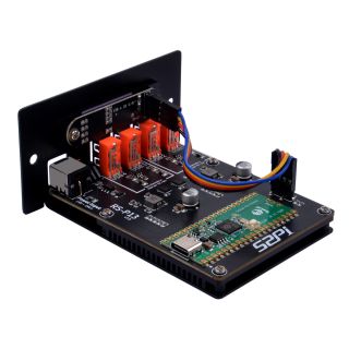
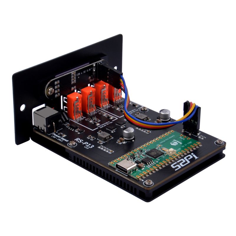
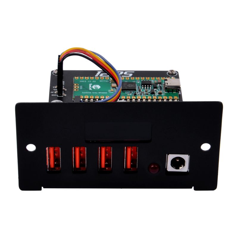
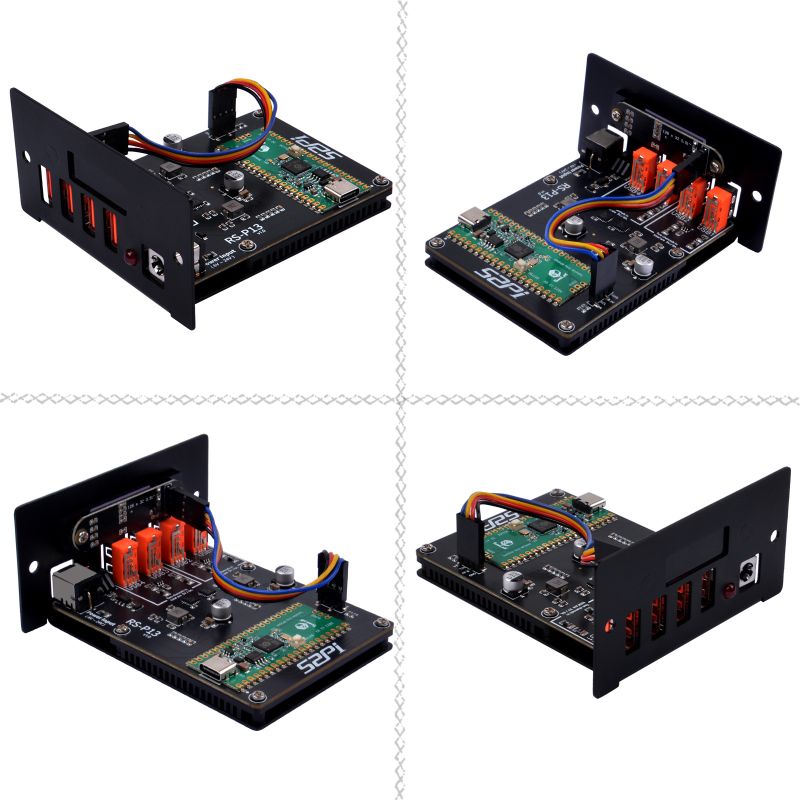
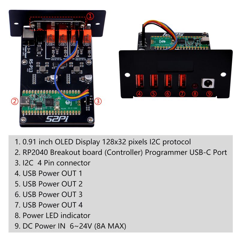
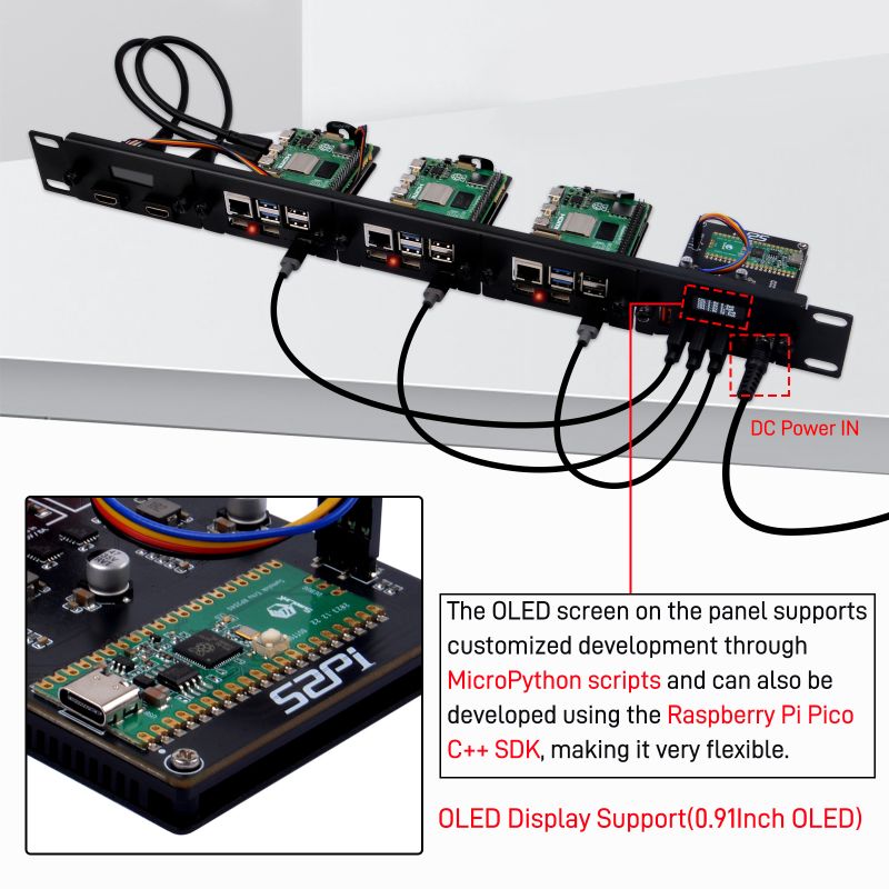
The PowerHub 4 USB-Channel 5V Power Supply module is an advanced power management module designed for versatile applications. It features a robust metal casing that ensures durability and protection. This module is not only a standalone power solution but also integrates seamlessly with DeskPi's Rackmate T0 or Rackmate T1 enclosures, making it suitable for 1U rack mounting. This allows for a unified power supply management system in a rack environment.
Features
- Metal Casing: Provides a sturdy and protective shell for the power module.
- RackMount Compatibility: Can be integrated into a 1U rack system using DeskPi's Rackmate T0 or T1 enclosures.
- 2-Channel Power Distribution: Capable of handling multiple devices with a maximum output of 8A in total.
- Dual USB Ports per Channel: Each channel features two USB ports sharing a maximum current of 8A.
- INA3221 Monitoring: Utilizes two INA3221 chips for precise voltage and current detection.
- OLED Display Interface: Equipped with a 0.91-inch OLED screen for displaying power output information.
- Raspberry Pi Pico Compatibility: Designed to work with a Raspberry Pi Pico for advanced control and customization through I2C communication.
- Programmable Output Information: Customizable display content through MicroPython scripting or C++ SDK.
- Wide Input Voltage Range: Accepts a wide range of input voltages from 6V to 24V.
Specifications
- Input Voltage: 6-24V DC,The inner diameter of the DC port: 5.44mm
- Maximum Current: 8A per channel (Shared by 4 x USB ports)
- Output Channels: 2 channels with dual USB ports each, totaling 4 USB ports
- Monitoring Chips: Two INA3221 chips for voltage and current monitoring
- Display: 0.91-inch OLED screen for real-time power output information. Default I2C address: 0x3c
- Control Interface: I2C interface for communication with Raspberry Pi Pico
- Programming: Supports MicroPython for scripting and C++ SDK for advanced customization
- Safety Features: Built-in protection mechanisms to prevent overcurrent and overheating
- Metal Casing:Adds to the durability and allows for rack mounting
- RackMount Compatibility: Compatible with DeskPi Rackmate T0 or T1 for 1U rack mounting
- Shunt Resister: 6mR
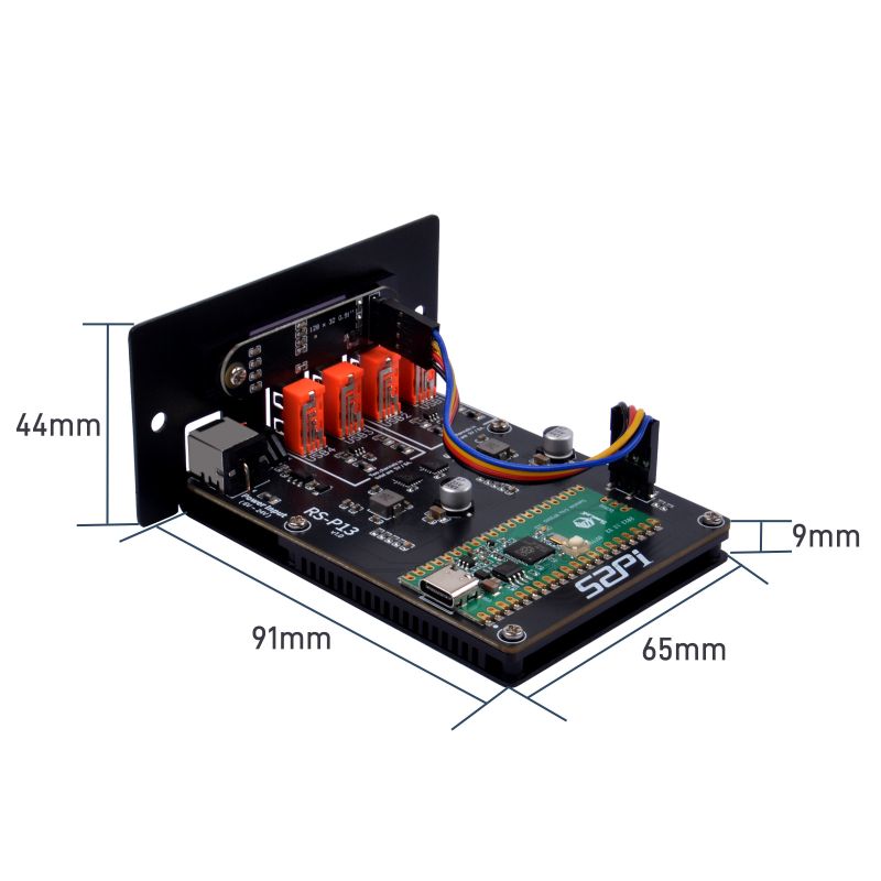
- Dimensions: 90mm x 88mm x 45mm
- Weight: 0.155kg
Gallery
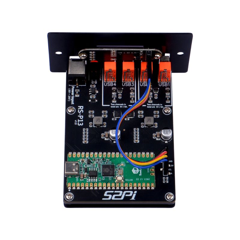
- Product Outlook
- Frontal face outlook
- Product details
- Dimension
- Aluminum Passive Heat dissipation heat-sink
- Pico main controller support MicroPython reprogrammable and C++ SDK
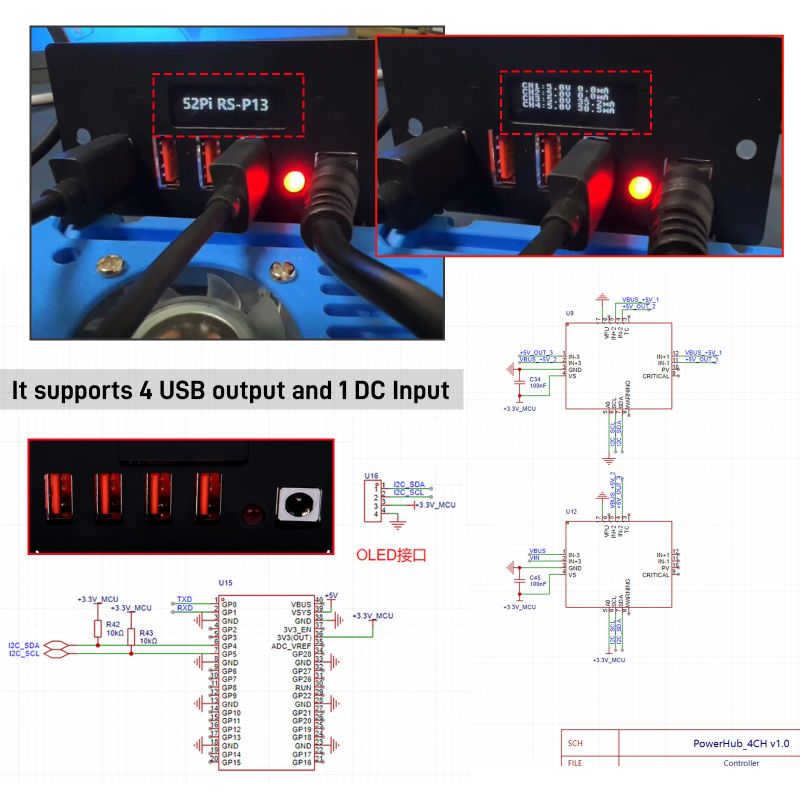
- Open-Source Design
- Application scenario
- Compatiable with DeskPi Rackmate's rack mount
- Circuit Schema Drawing
Package Includes
- Package includes
How to install or update MicroPython firmware?
- Download `Thonny IDE` software from internet and install it on your computer.
- [Download Thonny IDE https://thonny.org/]
- Please install it as following figures.
How to read the voltage and current?
Support MicroPython Only right now
- Install micropython firmware Steps
1. Put your device into bootloader mode: Device have to be plugged in while holding the `BOOTSEL` button. 2. Wait for couple of seconds until the target volume appears. 3. Select desired variant and version. 4. Click `install` and wait for some seconds until done. 5. Close the dialog and start programming!
Install microPython firmware
- Open thonny IDE and Click `run` and `configure interpreter`,select `MicroPython (Raspberry Pi Pico)`
- Click `install or update MicroPython` and then follow following figures:
Reopen the menu by click `run` and `configure interpreter`, select the right serial port for programming, here is mine:
Upload dependencies libraries
- INA3221.py
Open a new file, copy and paste following code, and the library file can be found below 'ina3221.zip' file,should be unzipped before using. if you use copy-paste way, please name it to `ina3221.py`
from machine import I2C, Pin, Timer
from micropython import const
import time

_REG_CONFIG                      = const(0x00)

_RESET                           = const(0x8000)
_ENABLE_CH                       = (None,const(0x4000),const(0x2000),const(0x1000)) # default set

_AVERAGING_MASK                  = const(0x0E00)
_AVERAGING_NONE                  = const(0x0000)     # 1 sample, default
_AVERAGING_4_SAMPLES             = const(0x0200)
_AVERAGING_16_SAMPLES            = const(0x0400)
_AVERAGING_64_SAMPLES            = const(0x0600)
_AVERAGING_128_SAMPLES           = const(0x0800)
_AVERAGING_256_SAMPLES           = const(0x0A00)
_AVERAGING_512_SAMPLES           = const(0x0C00)
_AVERAGING_1024_SAMPLES          = const(0x0E00)

_VBUS_CONV_TIME_MASK             = const(0x01C0)
_VBUS_CONV_TIME_140US            = const(0x0000)
_VBUS_CONV_TIME_204US            = const(0x0040)
_VBUS_CONV_TIME_332US            = const(0x0080)
_VBUS_CONV_TIME_588US            = const(0x00C0)
_VBUS_CONV_TIME_1MS              = const(0x0100)     # 1.1ms, default
_VBUS_CONV_TIME_2MS              = const(0x0140)     # 2.116ms
_VBUS_CONV_TIME_4MS              = const(0x0180)     # 4.156ms
_VBUS_CONV_TIME_8MS              = const(0x01C0)     # 8.244ms

_SHUNT_CONV_TIME_MASK            = const(0x0038)
_SHUNT_CONV_TIME_140US           = const(0x0000)
_SHUNT_CONV_TIME_204US           = const(0x0008)
_SHUNT_CONV_TIME_332US           = const(0x0010)
_SHUNT_CONV_TIME_588US           = const(0x0018)
_SHUNT_CONV_TIME_1MS             = const(0x0020)     # 1.1ms, default
_SHUNT_CONV_TIME_2MS             = const(0x0028)     # 2.116ms
_SHUNT_CONV_TIME_4MS             = const(0x0030)     # 4.156ms
_SHUNT_CONV_TIME_8MS             = const(0x0038)     # 8.244ms

_MODE_MASK                       = const(0x0007)
_MODE_POWER_DOWN                 = const(0x0000)     # Power-down
_MODE_SHUNT_VOLTAGE_TRIGGERED    = const(0x0001)     # Shunt voltage, single-shot (triggered)
_MODE_BUS_VOLTAGE_TRIGGERED      = const(0x0002)     # Bus voltage, single-shot (triggered)
_MODE_SHUNT_AND_BUS_TRIGGERED    = const(0x0003)     # Shunt and bus, single-shot (triggered)
_MODE_POWER_DOWN2                = const(0x0004)     # Power-down
_MODE_SHUNT_VOLTAGE_CONTINUOUS   = const(0x0005)     # Shunt voltage, continous
_MODE_BUS_VOLTAGE_CONTINUOUS     = const(0x0006)     # Bus voltage, continuous
_MODE_SHUNT_AND_BUS_CONTINOUS    = const(0x0007)     # Shunt and bus, continuous (default)

# Other registers
_REG_SHUNT_VOLTAGE_CH            = (None, const(0x01), const(0x03), const(0x05))
_REG_BUS_VOLTAGE_CH              = (None, const(0x02), const(0x04), const(0x06))
_REG_CRITICAL_ALERT_LIMIT_CH     = (None, const(0x07), const(0x09), const(0x0B))
_REG_WARNING_ALERT_LIMIT_CH      = (None, const(0x08), const(0x0A), const(0x0C))
_REG_SHUNT_VOLTAGE_SUM           = const(0x0D)
_REG_SHUNT_VOLTAGE_SUM_LIMIT     = const(0x0E)

# Mask/enable register
_REG_MASK_ENABLE                 = const(0x0F)
_SUM_CONTROL_CH                  = (None,const(0x4000),const(0x2000),const(0x1000)) #default not set
_WARNING_LATCH_ENABLE            = const(0x0800)     # default not set
_CRITICAL_LATCH_ENABLE           = const(0x0400)     # default not set
_CRITICAL_FLAG_CH                = (None,const(0x0200),const(0x0100),const(0x0080))
_SUM_ALERT_FLAG                  = const(0x0040)
_WARNING_FLAG_CH                 = (None,const(0x0020),const(0x0010),const(0x0008))
_POWER_ALERT_FLAG                = const(0x0004)
_TIMING_ALERT_FLAG               = const(0x0002)
_CONV_READY_FLAG                 = const(0x0001)

# Other registers
_REG_POWER_VALID_UPPER_LIMIT     = const(0x10)
_REG_POWER_VALID_LOWER_LIMIT     = const(0x11)
_REG_MANUFACTURER_ID             = const(0xFE)
_REG_DIE_ID                      = const(0xFF)

# Constants for manufacturer and device ID
_MANUFACTURER_ID                 = const(0x5449)     # "TI"
_DIE_ID                          = const(0x3220)


INA3221_I2C_ADDR = const(64)
INA3221_REG_MASK = const(0x0f)
INA3221_REG_ID = const(0xff)
#R_SHUNT = [100, 100, 100]
R_SHUNT = [0.006, 0.006, 0.006]

class INA3221:
    def __init__(self, i2c,addr = INA3221_I2C_ADDR):
        self.addr = addr
        self.i2c = i2c
        self.buf = bytearray(2)
    def getVShunt(self, chl_num = 0):
        """Get shunt resister voltage"""
        reg = 1 + chl_num * 2
        v_shunt_raw = self.i2c.readfrom_mem(self.addr, reg, 2)
        return v_shunt_raw[0], v_shunt_raw[1]

    def getIShunt(self, chl_num=0):
        """get chl_num current"""
        v_shunt_raw = self.getVShunt(chl_num)
        i_shunt = (v_shunt_raw[0] << 8) | v_shunt_raw[1]
        if v_shunt & 0x8000:
            v_shunt = -((~v_shunt +1 ) & 0xFFFF)
        v_shunt = v_shunt * 40 / 1000000
        i_shunt = v_shunt / R_SHUNT[chl_num]
        return i_shunt

    def getVBusRaw(self, chl_num = 0):
        """Get raw input voltage data"""
        reg = (chl_num + 1)* 2
        v_bus_raw = self.i2c.readfrom_mem(self.addr, reg, 2)
        return v_bus_raw

    def getVBus(self, chl_num = 0):
        """Get Input voltage"""
        v_bus_raw = self.getVBusRaw(chl_num)
        v_bus = v_bus_raw[0]  * 256 + v_bus_raw[1]
        return v_bus


    def getIShunt(self, chl_num = 0):
        """Get chl_num current"""
        v_shunt_raw = self.getVShunt(chl_num)
        v_shunt = v_shunt_raw[1] * 5 + v_shunt_raw[0] * 1280
        i_shunt = v_shunt / R_SHUNT[chl_num]
        return i_shunt

    def getI(self,chl_num=0,avg=20):
        """Get current,default 1ms get once,20ms detect the current, 0.02s detect once"""
        a=0
        for i in range(avg):
            i_o=self.getIShunt(chl_num)
            a=a + i_o
            time.sleep_ms(1)
        return round(a / avg, 1)
- Save it to Raspberry Pi Pico's `lib` folder
If no `lib` folder, right click and create one.
and then enter into the `lib` folder and save the library file as `ina3221.py`.
- Download ina3221.py zipped file: File:Ina3221.zip
- Upload OLED driver `ssd1306.py`
This library is to light up 0.91 inch OLED display, please use the same way to upload the library. make sure it looks like this:
Following is the content of `ssd1306.py` file.
# MicroPython SSD1306 OLED driver, I2C and SPI interfaces

from micropython import const
import framebuf


# register definitions
SET_CONTRAST = const(0x81)
SET_ENTIRE_ON = const(0xA4)
SET_NORM_INV = const(0xA6)
SET_DISP = const(0xAE)
SET_MEM_ADDR = const(0x20)
SET_COL_ADDR = const(0x21)
SET_PAGE_ADDR = const(0x22)
SET_DISP_START_LINE = const(0x40)
SET_SEG_REMAP = const(0xA0)
SET_MUX_RATIO = const(0xA8)
SET_COM_OUT_DIR = const(0xC0)
SET_DISP_OFFSET = const(0xD3)
SET_COM_PIN_CFG = const(0xDA)
SET_DISP_CLK_DIV = const(0xD5)
SET_PRECHARGE = const(0xD9)
SET_VCOM_DESEL = const(0xDB)
SET_CHARGE_PUMP = const(0x8D)

# Subclassing FrameBuffer provides support for graphics primitives
# http://docs.micropython.org/en/latest/pyboard/library/framebuf.html
class SSD1306(framebuf.FrameBuffer):
    def __init__(self, width, height, external_vcc):
        self.width = width
        self.height = height
        self.external_vcc = external_vcc
        self.pages = self.height // 8
        self.buffer = bytearray(self.pages * self.width)
        super().__init__(self.buffer, self.width, self.height, framebuf.MONO_VLSB)
        self.init_display()

    def init_display(self):
        for cmd in (
            SET_DISP | 0x00,  # off
            # address setting
            SET_MEM_ADDR,
            0x00,  # horizontal
            # resolution and layout
            SET_DISP_START_LINE | 0x00,
            SET_SEG_REMAP | 0x01,  # column addr 127 mapped to SEG0
            SET_MUX_RATIO,
            self.height - 1,
            SET_COM_OUT_DIR | 0x08,  # scan from COM[N] to COM0
            SET_DISP_OFFSET,
            0x00,
            SET_COM_PIN_CFG,
            0x02 if self.width > 2 * self.height else 0x12,
            # timing and driving scheme
            SET_DISP_CLK_DIV,
            0x80,
            SET_PRECHARGE,
            0x22 if self.external_vcc else 0xF1,
            SET_VCOM_DESEL,
            0x30,  # 0.83*Vcc
            # display
            SET_CONTRAST,
            0xFF,  # maximum
            SET_ENTIRE_ON,  # output follows RAM contents
            SET_NORM_INV,  # not inverted
            # charge pump
            SET_CHARGE_PUMP,
            0x10 if self.external_vcc else 0x14,
            SET_DISP | 0x01,
        ):  # on
            self.write_cmd(cmd)
        self.fill(0)
        self.show()

    def poweroff(self):
        self.write_cmd(SET_DISP | 0x00)

    def poweron(self):
        self.write_cmd(SET_DISP | 0x01)

    def contrast(self, contrast):
        self.write_cmd(SET_CONTRAST)
        self.write_cmd(contrast)

    def invert(self, invert):
        self.write_cmd(SET_NORM_INV | (invert & 1))

    def show(self):
        x0 = 0
        x1 = self.width - 1
        if self.width == 64:
            # displays with width of 64 pixels are shifted by 32
            x0 += 32
            x1 += 32
        self.write_cmd(SET_COL_ADDR)
        self.write_cmd(x0)
        self.write_cmd(x1)
        self.write_cmd(SET_PAGE_ADDR)
        self.write_cmd(0)
        self.write_cmd(self.pages - 1)
        self.write_data(self.buffer)


class SSD1306_I2C(SSD1306):
    def __init__(self, width, height, i2c, addr=0x3C, external_vcc=False):
        self.i2c = i2c
        self.addr = addr
        self.temp = bytearray(2)
        self.write_list = [b"\x40", None]  # Co=0, D/C#=1
        super().__init__(width, height, external_vcc)

    def write_cmd(self, cmd):
        self.temp[0] = 0x80  # Co=1, D/C#=0
        self.temp[1] = cmd
        self.i2c.writeto(self.addr, self.temp)

    def write_data(self, buf):
        self.write_list[1] = buf
        self.i2c.writevto(self.addr, self.write_list)


class SSD1306_SPI(SSD1306):
    def __init__(self, width, height, spi, dc, res, cs, external_vcc=False):
        self.rate = 10 * 1024 * 1024
        dc.init(dc.OUT, value=0)
        res.init(res.OUT, value=0)
        cs.init(cs.OUT, value=1)
        self.spi = spi
        self.dc = dc
        self.res = res
        self.cs = cs
        import time

        self.res(1)
        time.sleep_ms(1)
        self.res(0)
        time.sleep_ms(10)
        self.res(1)
        super().__init__(width, height, external_vcc)

    def write_cmd(self, cmd):
        self.spi.init(baudrate=self.rate, polarity=0, phase=0)
        self.cs(1)
        self.dc(0)
        self.cs(0)
        self.spi.write(bytearray([cmd]))
        self.cs(1)

    def write_data(self, buf):
        self.spi.init(baudrate=self.rate, polarity=0, phase=0)
        self.cs(1)
        self.dc(1)
        self.cs(0)
        self.spi.write(buf)
        self.cs(1)
- Download ssd1306.py zipped file: File:Ssd1306.zip
NOTE: Unzip it before upload it to Raspberry Pi Pico
Demo code
- Create a new file and copy and paste following demo code into it.
from machine import Pin, I2C, ADC
from ssd1306 import SSD1306_I2C
import framebuf
import time
import ina3221
from math import floor

WIDTH = 128
HEIGHT = 32

# logo
buffer = bytearray(b'\x00\x00\x00\x00\x00\x00\x00\x00\x00\x00\x00\x00\x00\x00\x00\x00\x00\x00\x00\x00\x00\x00\x00\x00\x00\x00\x00\x00\x00\x00\x00\x00\x00\x00\x00\x00\x00\x00\x00\x00\x00\x00\x00\x00\x00\x00\x00\x00\x00\x00\x00\x00\x00\x00\x00\x00\x00\x00\x00\x00\x00\x00\x00\x00\x00\x00\x00\x00\x00\x00\x00\x00\x00\x00\x00\x00\x00\x00\x00\x00\x00\x00\x00\x00\x00\x00\x00\x00\x00\x00\x00\x00\x00\x00\x00\x00\x00\x00\x00\x00\x00\x00\x00\x00\x00\x00\x00\x00\x00\x00\x00\x00\x00\x00\x00\x00\x00\x00\x00\x00\x00\x00\x00\x00\x00\x00\x00\x00\x00\x00\x00\x00\x00\x00\x00\x00\x00\x00\x00\x00\x00\x00\x00\x00\x00\x00\x00\x00\x01\x80\x00\x00\x00\x00\x00\x00\x00\x00\x00\x00\x1f\xe3\xf8?\xc3\xc0\x1f\xe0?\xc0\x03\xfc\x03\xc1\xfc\x00?\xc3\xfc?\xf1\xc0\x1f\xf8\x7f\x80\x03\xff\x0f\x81\xfe\x00\x18C\x1e9\xf0\x00\x1cx\xf0\xc0\x03\x9f\x1f\xc0\x0f\x008\x00\x0exx\x00\x1c<\xe0\x00\x03\x87\x9d\x80\x0f\x008\x00\x0e8s\x80\x1c8\xf0\x00\x03\x87\x03\xc0\x06\x00:\x00\x1e8y\xc0\x1c8x\x00\x03\x87\x81\x80\x0e\x00?\xc0\x1c8s\x80\x1dx~\x00\x03\x87\x03\xc0\xfc\x00?\xc0<?\xf1\xc0\x1f\xe0?\x80\x03\xff\x03\x80\xfc\x00\x01\xe0\xf8?\xc3\x80\x1f\xe0\x0f\x87\xc3\xfc\x01\xc0>\x00\x00\xe1\xe0\x7f\x01\xc0\x1c\xf0\x03\xcf\xc7\xf0\x03\x80\x07\x00\x00\xe3\xc08\x03\x80\x1cp\x01\xc0C\x80\x01\xc0\x07\x00\x00\xe7\x808\x03\xc0\x1cx\x81\xc0\x03\x80\x03\x80\x07\x00!\xe7\xba8\x01\x80\x1c<\xd7\xc0\x03\x80\x01\xc1\x1f\x00?\xc7\xfe8\x03\xc0\x1c\x1c\xff\x80\x03\x80\x03\x83\xfe\x00?\x87\xfex\x01\x80\x1c\x1e\x7f\x00\x07\x80\x03\xc1\xfc\x00\x00\x00\x00\x00\x00\x00\x00\x00\x00\x00\x00\x00\x00\x00\x00\x00\x00\x00\x00\x00\x00\x00\x00\x00\x00\x00\x00\x00\x00\x00\x00\x00\x00\x00\x00\x00\x00\x00\x00\x00\x00\x00\x00\x00\x00\x00\x00\x00\x00\x00\x00\x00\x00\x00\x00\x00\x00\x00\x00\x00\x00\x00\x00\x00\x00\x00\x00\x00\x00\x00\x00\x00\x00\x00\x00\x00\x00\x00\x00\x00\x00\x00\x00\x00\x00\x00\x00\x00\x00\x00\x00\x00\x00\x00\x00\x00\x00\x00\x00\x00\x00\x00\x00\x00\x00\x00\x00\x00\x00\x00\x00\x00')
fb = framebuf.FrameBuffer(buffer, 128, 32, framebuf.MONO_HLSB)

i2c = I2C(0, scl=Pin(5), sda=Pin(4),freq=200000)

print(i2c.scan())

oled = SSD1306_I2C(WIDTH, HEIGHT, i2c, addr=0x3C)

INA3221_ADDR1 = hex(i2c.scan()[1])
INA3221_ADDR2 = hex(i2c.scan()[2])
print(INA3221_ADDR1)
print(INA3221_ADDR2)

# create instance of ina3221 chip.  0x41 and 0x40 are the register address of the chip.
ina1 = ina3221.INA3221(i2c, 0x41)
ina2 = ina3221.INA3221(i2c, 0x40)
# clear screen
oled.fill(0)

oled.invert(0)
oled.fill(0)
oled.blit(fb, 0, 0)
oled.show()
time.sleep(5)
oled.fill(0)
# Put text on screen
#oled.text("Hello World", 0, 0)
while True:

    vbus1 = ina2.getVBus(0) / 1000.0  # 5v
    vbus2 = ina2.getVBus(1) / 1000.0  # 5v
    vbus3 = ina2.getVBus(2) / 1000.0  # total 32v
    vbus4 = ina1.getVBus(1) / 1000.0 # 12v

    ch1_current = ina2.getI(chl_num=0)
    ch2_current = ina2.getI(chl_num=1)
    ch3_current = ina2.getI(chl_num=2)
    ch4_current = ina1.getI(chl_num=1)


    oled.text(f"CH1:{vbus1:.1f}V", 0, 0)
    oled.text(f" {ch1_current /1000000.0:.1f}A", 64,0)

    oled.text(f"CH2:{vbus2:.1f}V", 0, 8)
    oled.text(f" {ch2_current /1000000.0:.1f}A", 64,8)

    oled.text(f"CH3:{vbus3:.1f}V", 0, 16)
    oled.text(f" {ch3_current/1000000.0:.1f}A", 64,16)

    oled.text(f"CH4:{vbus4:.1f}V", 0, 24)
    oled.text(f" {ch4_current/1000000.0:.1f}A", 64,24)
    oled.show()
    time.sleep(3)
    oled.fill(0)
    I_shunt0 = ina2.getIShunt(0)
    I_shunt1 = ina2.getIShunt(1)
    I_shunt2 = ina2.getIShunt(2)
    I_shunt3 = ina1.getIShunt(0)
    I_shunt4 = ina1.getIShunt(1)
    I_shunt5 = ina1.getIShunt(2)
    oled.text(f"V0:{(I_shunt0 / 1000000.0):.2f}A",0, 0)
    print(I_shunt0)
    oled.text(f"I1:{(I_shunt1 / 1000000.0):.2f}A",68, 0)
    oled.text(f"I2:{(I_shunt2 / 1000000.0):.2f}A",0, 8)
    oled.text(f"I3:{(I_shunt3 / 1000000.0):.2f}A",68, 8)
    oled.text(f"I4:{(I_shunt4 / 1000000.0):.2f}A",0, 16)
    oled.text(f"I5:{(I_shunt5 / 1000000.0):.2f}A",68, 16)
    oled.show()
    time.sleep(3)
    oled.fill(0)
Save it as "main.py" to Raspberry Pi Pico or test it by click play button on thonny menu. It will measure the voltage and current on each USB port, you can change the democode to fit for your own request.
YouTuBe Tutorial
- YoutuBe Tutorial URL: [[ https://youtu.be/uHrA0ky3zVA ]]
