D-0011
Stepper Motor
Description
A stepper motor, also known as step motor or stepping motor, is a brushless DC electric motor that divides a full rotation into a number of equal steps.
The motor's position can then be commanded to move and hold at one of these steps without any position sensor for feedback, as long as the motor is carefully sized to the application in respect to torque and speed.
Features
- Small step angle
- High positioning accuracy
- High torque to inertia ratio
- Stepping rate and accuracy
Small Step Angle
The angle by which the rotor of a stepper motor moves when one pulse is applied to the (input) stator is called step angle. This is expressed in degrees. The resolution of positioning of a stepper motor is decided by the step angle. Smaller the step angle the higher is the resolution of positioning of the motor. The step number of a motor is the number of steps it makes in one revolution. The stepper motors are realisable for very small step angle. Some precision motors can make 1000 steps in one revolution with a step angle of 0.36°. A standard motor will have a step angle of 1.8° with 200 steps for revolution. The step angles of 90°, 45°, 15° are not uncommon in simple motors.
High Positioning Accuracy
The quality of a stepper motor is decided by its positioning accuracy. This accuracy of positioning is a significant factor. In any application the stepper motors are expected to rotate by step angle when a pulse is given as input. It should come to rest in a precise position. Care must be exercised in the design and manufacture of a stepper motor as the accuracy at no load depends on the physical accuracy of the rotor and the stator. The positioning accuracy depends only on the machine characteristics and the driving circuit, while other electronic parameters have no effect on positioning accuracy. The stepper motors are designed to have very high restoring torque when the rotor is displaced following load torque.
High Torque-to-inertia Ratio
A stepper motor must move fast response to a pulse or a train of pulses. Fast response is also associated with quick start and quick stop of the motor. The motor must be capable of stopping at a position specified by the last pulse of the pulse train if the train is inhibited when the motor is running uniformly. A stepper motor must have a large ratio of torque to inertia.
Stepping Rate and Pulse Frequency
The speed of a stepper motor is indicated by the number of pulses per second. Stepping rate of the motor is therefore used to indicate the speed. As the motor moves by one step for a pulse the speed can also be indicated by pulses per second as pulse frequency. The absolute rotational speed and stepping rate are related by.
Specifications
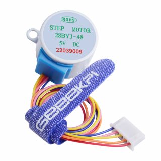
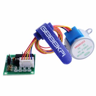
- Stepper Motor Type: 28BYJ-48
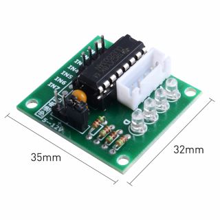
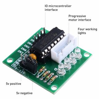
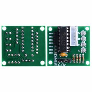
- Driver Board: ULN2003AN
- A, B, C, D four-phase LED indicates the status of the stepper motor work.
- Stepper motor with a standard interface, when used directly pluggable.
- 5 line 4 phase can be used for ordinary ULN2003 chip driver, connect to the 2 phase , support the development board, with convenient use, direct docking.
- Rated Voltage: DC5V 4-phase
- Insulation Resistance: >10MΩ (500V)
- Dielectric Strength: 600V AC / 1mA / 1s
- Step angle: 5.625 x 1/64
- DC Resistance: 200Ω±7% (25C)
- Reduction ratio: 1/64
- Insulation Grade: A
- No-load Pull in Frequency: >600Hz
- No-load Pull out Frequency: >1000Hz
- Pull in Torque: >34.3mN.m(120Hz)
- Detent Torque: >34.3mN.m
- Temperature Rise: < 40K(120Hz)
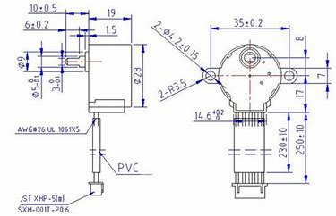
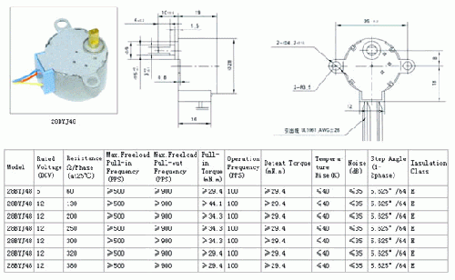
Mechanical Drawing
28BYJ-48-Model-Series
Gallery
Application Scenario
- Arduino
- Programm Code Example
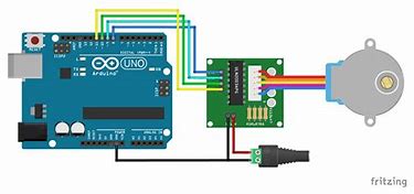
The Arduino IDE support a library for stepper motor, after connect motor with microcontroller you can upload the sketch on to the microcontroller.
The following is the code of an example program, it can be modified according to your needs:
#define IN1 8
#define IN2 9
#define IN3 10
#define IN4 11
int Steps = 0;
boolean Direction = true;
void setup() {
     Serial.begin(9600);
     pinMode(IN1, OUTPUT);
     pinMode(IN2, OUTPUT);
     pinMode(IN3, OUTPUT);
     pinMode(IN4, OUTPUT);
}
void loop() {
    for(int i=0; i<4096; i++){
        stepper(1);
        delayMicroseconds(800);
        }
    Direction = !Direction;
}

void stepper(int xw) {
     for (int x = 0; x < xw; x++) {
        switch (Steps) {
             case 0:
                  digitalWrite(IN1, LOW);
                  digitalWrite(IN2, LOW);
                  digitalWrite(IN3, LOW);
                  digitalWrite(IN4, HIGH);
                  break;
             case 1:
                  digitalWrite(IN1, LOW);
                  digitalWrite(IN2, LOW);
                  digitalWrite(IN3, HIGH);
                  digitalWrite(IN4, HIGH);
                  break;
             case 2:
                  digitalWrite(IN1, LOW);
                  digitalWrite(IN2, LOW);
                  digitalWrite(IN3, HIGH);
                  digitalWrite(IN4, LOW);
                  break;
             case 3:
                  digitalWrite(IN1, LOW);
                  digitalWrite(IN2, HIGH);
                  digitalWrite(IN3, HIGH);
                  digitalWrite(IN4, LOW);
                  break;
             case 4:
                  digitalWrite(IN1, LOW);
                  digitalWrite(IN2, HIGH);
                  digitalWrite(IN3, LOW);
                  digitalWrite(IN4, LOW);
                  break;
             case 5:
                  digitalWrite(IN1, HIGH);
                  digitalWrite(IN2, HIGH);
                  digitalWrite(IN3, LOW);
                  digitalWrite(IN4, LOW);
                  break;
             case 6:
                  digitalWrite(IN1, HIGH);
                  digitalWrite(IN2, LOW);
                  digitalWrite(IN3, LOW);
                  digitalWrite(IN4, LOW);
                  break;
             case 7:
                  digitalWrite(IN1, HIGH);
                  digitalWrite(IN2, LOW);
                  digitalWrite(IN3, LOW);
                  digitalWrite(IN4, HIGH);
                  break;
             default:
                  digitalWrite(IN1, LOW);
                  digitalWrite(IN2, LOW);
                  digitalWrite(IN3, LOW);
                  digitalWrite(IN4, LOW);
                  break;
                  }
       SetDirection();
      }
}
void SetDirection() {
    if (Direction == 1) {
        Steps++;
    }
    if (Direction == 0) {
        Steps--;
    }
    if (Steps > 7) {
        Steps = 0;
    }
    if (Steps < 0) {
        Steps = 7;
    }
}
- Raspberry Pi Demo Code
When using the 28BYJ–48, the sequence is as follows.
If you are using a different motor, you have to adjust the sequence corresponding to your data sheet.
- Datasheet: [ File:Stepper-Motor-28BJY-48-Datasheet.pdf]
- Open terminal and typing:
sudo nano stepper.py
and add the following script:
import RPi.GPIO as GPIO
import time

GPIO.setmode(GPIO.BCM)  # means you need to use BCM GPIO named system, you can use pinout command to get the pin's number information in command line.
GPIO.setwarnings(False)
coil_A_1_pin = 4 # pink - GPIO 4
coil_A_2_pin = 17 # orange - GPIO 17
coil_B_1_pin = 23 # blue - GPIO 23
coil_B_2_pin = 24 # yellow -GPIO 24

# adjust if different
StepCount = 8
Seq = range(0, StepCount)
Seq[0] = [0,1,0,0]
Seq[1] = [0,1,0,1]
Seq[2] = [0,0,0,1]
Seq[3] = [1,0,0,1]
Seq[4] = [1,0,0,0]
Seq[5] = [1,0,1,0]
Seq[6] = [0,0,1,0]
Seq[7] = [0,1,1,0]

GPIO.setup(enable_pin, GPIO.OUT)
GPIO.setup(coil_A_1_pin, GPIO.OUT)
GPIO.setup(coil_A_2_pin, GPIO.OUT)
GPIO.setup(coil_B_1_pin, GPIO.OUT)
GPIO.setup(coil_B_2_pin, GPIO.OUT)

GPIO.output(enable_pin, 1)

def setStep(w1, w2, w3, w4):
    GPIO.output(coil_A_1_pin, w1)
    GPIO.output(coil_A_2_pin, w2)
    GPIO.output(coil_B_1_pin, w3)
    GPIO.output(coil_B_2_pin, w4)

def forward(delay, steps):
    for i in range(steps):
        for j in range(StepCount):
            setStep(Seq[j][0], Seq[j][1], Seq[j][2], Seq[j][3])
            time.sleep(delay)

def backwards(delay, steps):
    for i in range(steps):
        for j in reversed(range(StepCount)):
            setStep(Seq[j][0], Seq[j][1], Seq[j][2], Seq[j][3])
            time.sleep(delay)

if __name__ == '__main__':
    while True:
        delay = raw_input("Time Delay (ms)?")
        steps = raw_input("How many steps forward? ")
        forward(int(delay) / 1000.0, int(steps))
        steps = raw_input("How many steps backwards? ")
        backwards(int(delay) / 1000.0, int(steps))
Then just save with CTRL+O and CTRL+X and quit. You can start it with:
sudo python stepper.py
With setStep(0,0,0,0) you can set the stepper to idle, because otherwise power is consumed all the time (by the electromagnets in the motor).
- NOTE:
Regard that if you choose a high delay value (per step), the motor is moving very slowly (e.g. with a 100ms delay one full turn would already take 51.2 seconds, because the engine has a total of 512 steps. Too small delay values may, however, have the opposite effect, so that the signals are transmitted too quickly and causing the motor to just “stuttering”. If you want a faster engine, choose a model with a larger step angle).
Package Includes
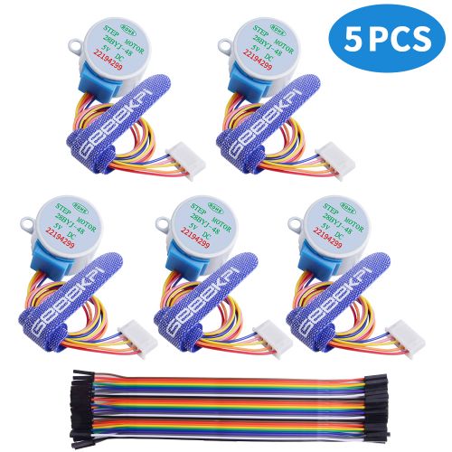
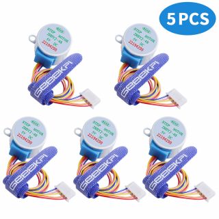
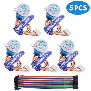
- 5 x Stepper Motor
- 5 x ULN2003AN Driver Board
- 30 x Female-to-female jump wire
Github Project
- Piday4Fun: [ https://github.com/Piday4Fun ]
Keywords
- 5V, Stepper motor, ULN2003AN
