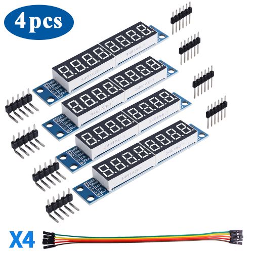
D-0009
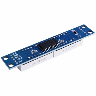
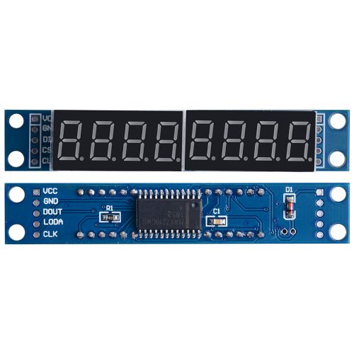
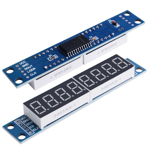
MAX7219 7-Segment Displays
Description
The MAX7219/MAX7221 are compact, serial input/output common-cathode display drivers that interface microprocessors (µPs) to 7-segment numeric LED displays of up to 8 digits, bar-graph displays, or 64 individual LEDs. Included on-chip are a BCD code-B decoder, multiplex scan circuitry, segment and digit drivers, and an 8x8 static RAM that stores each digit. Only one external resistor is required to set the segment current for all LEDs. The MAX7221 is compatible with SPI™, QSPI™, and MICROWIRE™, and has slew-rate-limited segment drivers to reduce EMI.
The MAX7219 chipset supports a serial 16-bit register/data buffer which is clocked in on pin DIN every time the clock edge falls, and clocked out on DOUT 16.5 clock cycles later.
This allows multiple devices to be chained together.
The devices include a 150µA low-power shutdown mode, analog and digital brightness control, a scan-limit register that allows the user to display from 1 to 8 digits, and a test mode that forces all LEDs on.
Features
- SPI driver
- Cascadable
- Supports dimming mode (PWM)
- Easy to drive
- Easy to install
- Digital tube with low power consumption
Specifications
- 10MHz Serial Interface
- Individual LED Segment Control
- Decode/No-Decode Digit Selection
- 150µA Low-Power Shutdown (Data Retained)
- Digital and Analog Brightness Control
- Display Blanked on Power-Up
- Drive Common-Cathode LED Display
- Slow-Rate Limited Segment Drivers for Lower EMI (MAX7221)
- SPI, QSPI, MICROWIRE Serial Interface (MAX7221)
Gallery
Application Scenario
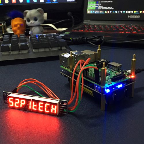
- Work with Raspberry Pi 4B
Package Includes
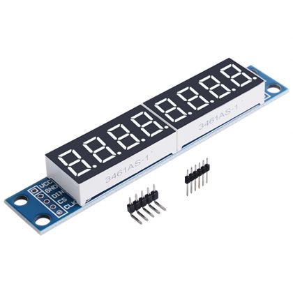
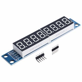
- 4 x MAX7219 7-Segment LED matrix
- 4 x 5Pin jumper wire
Documentations
- Python Driver: [ https://max7219.readthedocs.io/en/0.2.3/ ]
This library supports:
- multiple cascaded devices
- LED matrix and seven-segment variants
Python Usage
- For the matrix device, initialize the matrix class:
import max7219.led as led

device = led.matrix()
device.show_message("Hello world!")
- For the 7-segment device, initialize the sevensegment class:
import max7219.led as led

device = led.sevensegment()
device.write_number(deviceId=0, value=3.14159)
The MAX7219 chipset supports a serial 16-bit register/data buffer which is clocked in on pin DIN every time the clock edge falls, and clocked out on DOUT 16.5 clock cycles later. This allows multiple devices to be chained together.
When initializing cascaded devices, it is necessary to specify a cascaded=... parameter, and generally methods which target specific devices will expect a deviceId=... parameter, counting from zero.
Pre-requisites
By default, the SPI kernel driver is NOT enabled on the Raspberry Pi Raspian image.
- You can confirm whether it is enabled using the shell commands below:
$ lsmod | grep -i spi
spi_bcm2835             7424  0
Depending on the kernel version, this may report spi_bcm2807 rather than spi_bcm2835 - either should be adequate.
And that the devices are successfully installed in /dev:
$ ls -l /dev/spi*
crw------- 1 root root 153, 0 Jan  1  1970 /dev/spidev0.0
crw------- 1 root root 153, 1 Jan  1  1970 /dev/spidev0.1
- If you have no /dev/spi files and nothing is showing using lsmod then this implies the kernel SPI driver is not loaded. Enable the SPI as follows (steps taken from https://learn.sparkfun.com/tutorials/raspberry-pi-spi-and-i2c-tutorial#spi-on-pi):
1. Run sudo raspi-config
2. Use the down arrow to select 9 Advanced Options
3. Arrow down to A6 SPI.
4. Select yes when it asks you to enable SPI,
5. Also select yes when it asks about automatically loading the kernel module.
6. Use the right arrow to select the <Finish> button.
After rebooting re-check that the lsmod | grep -i spi command shows whether SPI driver is loaded before proceeding. If you are stil experiencing problems, refer to the official Raspberry Pi SPI troubleshooting guide for further details.
GPIO pin-outs
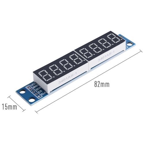
The breakout board has two headers to allow daisy-chaining:
Board Pin	Name	Remarks	RPi Pin	RPi Function
1	VCC	+5V Power	2	5V0
2	GND	Ground	6	GND
3	DIN	Data In	19	GPIO 10 (MOSI)
4	CS	Chip Select	24	GPIO 8 (SPI CE0)
5	CLK	Clock	23	GPIO 11 (SPI CLK)
Note: See below for cascading/daisy-chaining, power supply and level-shifting.
Installing the library
Note: The library has been tested against Python 2.7 and 3.4. For Python3 installation, substitute pip ⇒ pip3, python ⇒ python3, python-dev ⇒ python3-dev, and python-pip ⇒ python3-pip in the instructions below.
- Install the latest version of the library directly from PyPI:
$ sudo apt-get install python-dev python-pip
$ sudo pip install max7219
Alternatively, clone the code from github:
$ git clone https://github.com/rm-hull/max7219.git
$ cd max7219
$ sudo pip install -e .
Next, follow the specific steps below for your OS.
Raspbian
$ cd max7219
$ sudo apt-get install python-dev python-pip
$ sudo pip install spidev
$ sudo python setup.py install
Select yes when it asks to reboot.
Cascading, power supply & level shifting
The MAX7219 chip supports cascading devices by connecting the DIN of one chip to the DOUT of another chip. For a long time I was puzzled as to why this didnt seem to work properly for me, despite spending a lot of time investigating and always assuming it was a bug in code.
Because the Raspberry PI can only supply a limited amount of power from the 5V rail, it is recommended that any LED matrices are powered separately by a 5V supply, and grounded with the Raspberry PI. It is possible to power one or two LED matrices directly from a Raspberry PI, but any more is likely to cause intermittent faults & crashes.
Also because the GPIO ports used for SPI are 3.3V, a simple level shifter (as per the diagram below) should be employed on the DIN, CS and CLK inputs to boost the levels to 5V. Again it is possible to drive them directly by the 3.3V GPIO pins, it is just outside tolerance, and will result in intermittent issues.
max7219 levelshifter
Despite the above two points, I still had no success getting cascaded matrices to work properly. Revisiting the wiring, I had connected the devices in serial connecting the out pins of one device to the in pins of another. This just produced garbled images.
Connecting the CLK lines on the input side all together worked first time. I can only assume that there is some noise on the clock line, or a dry solder joint somewhere.
max7219 cascaded
If you have more than one device and they are daisy-chained together, you can initialize the library with:
import max7219.led as led

device = led.matrix(cascaded = 3)
device.show_message("Hello world!")
To address a specific device, most other methods expect a deviceId=N parameter (where N=0..cascaded-1).
Examples
Run the example code as follows:
$ sudo python examples/matrix_test.py
or:
$ sudo python examples/sevensegment_test.py
Note: By default, SPI is only accessible by root (hence using sudo above). Follow these instructions to create an spi group, and adding your user to that group, so you don’t have to run as root.
References
Contributing
Pull requests (code changes / documentation / typos / feature requests / setup) are gladly accepted. If you are intending some large-scale changes, please get in touch first to make sure we’re on the same page: try and include a docstring for any new methods, and try and keep method bodies small, readable and PEP8-compliant.
Contributors
- Thijs Triemstra (@thijstriemstra)
- Jon Carlos (@webmonger)
- Unattributed (@wkapga)
- Taras (@tarasius)
- Brice Parent (@agripo)
License
The MIT License (MIT)
Copyright (c) 2016 Richard Hull<br>

Permission is hereby granted, free of charge, to any person obtaining a copy of this software and associated documentation files (the “Software”), to deal in the Software without restriction, including without limitation the rights to use, copy, modify, merge, publish, distribute, sublicense, and/or sell copies of the Software, and to permit persons to whom the Software is furnished to do so, subject to the following conditions:

The above copyright notice and this permission notice shall be included in all copies or substantial portions of the Software.

THE SOFTWARE IS PROVIDED “AS IS”, WITHOUT WARRANTY OF ANY KIND, EXPRESS OR IMPLIED, INCLUDING BUT NOT LIMITED TO THE WARRANTIES OF MERCHANTABILITY, FITNESS FOR A PARTICULAR PURPOSE AND NONINFRINGEMENT. IN NO EVENT SHALL THE AUTHORS OR COPYRIGHT HOLDERS BE LIABLE FOR ANY CLAIM, DAMAGES OR OTHER LIABILITY, WHETHER IN AN ACTION OF CONTRACT, TORT OR OTHERWISE, ARISING FROM, OUT OF OR IN CONNECTION WITH THE SOFTWARE OR THE USE OR OTHER DEALINGS IN THE SOFTWARE.
Keywords
- Max7219 LED matrix, led matrix, Raspberry Pi 4B
