K-0592
Mini Tower UPS Kit
Description
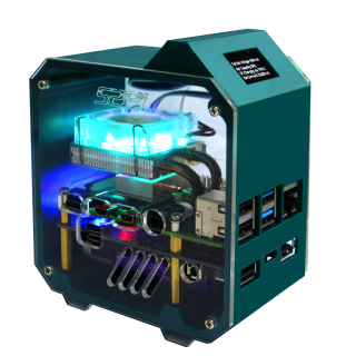
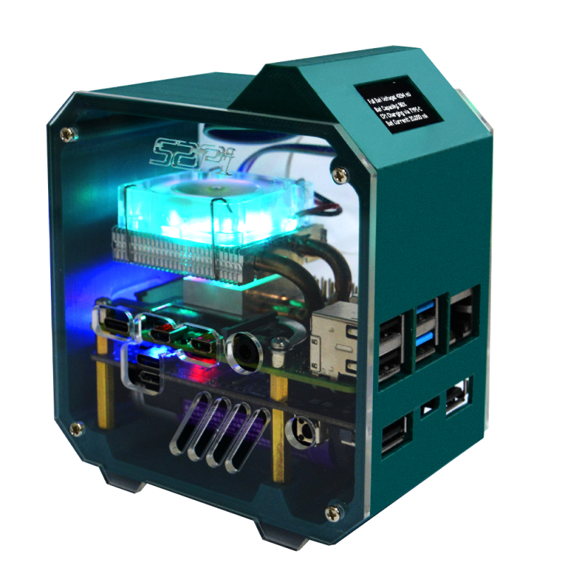
This is a 3D printed Case for Raspberry Pi 4B and UPS PLUS. The material of case is made of PLA, and the side is made of transparent acrylic material. Ice tower cooler can be placed into the case with Raspberry Pi 4B and UPS Plus. The 0.96 inch OLED screen provided in kit can display the running status of Raspberry Pi or UPS Plus through programming.
Note: Since the case is printed by FDM 3D printer and is made of PLA material, the surface of the case will have a little roughness, which is normal and does not affect the use. If necessary, you can polish it by yourself.
Raspberry Pi 4B does not include in the package!!
Features
- Support Raspberry Pi 4B only
- Easy to assemble
- Support OLED display
- Support UPS Plus integration
- Support ICE Tower Cooler integration
- Good appearance
- Compact mini
Gallery
- Product Outlook
- New Features
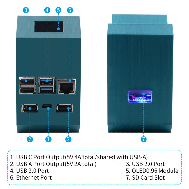
- Definition of Ports
- UPS Plus
Package Includes
- 1 x 3D printing Case
- 2 x Acrylic side panel
- 2 x 0.96 inch OLED Display and jumper wires
- 1 x UPS Plus Module with screws and copper pillars
- 1 x Low profile Ice tower cooler kit
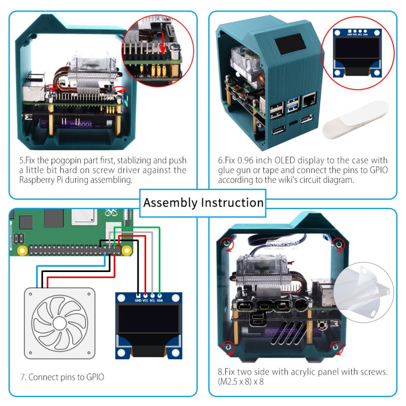
How to assemble
- 1. Fix the copper pillar to 3D printing case.
- 2. Fix UPS Plus with short copper pillar.
- 3. Fix Raspberry Pi 4B with short copper pillar and make sure the pogopin is against to the GPIO Pin.
- 4. Fix the metal bracket of low profile ice tower cooler with M2.5 screws.
- 5. Fix low profile ice tower cooler to Raspberry Pi with M2.5 screws.
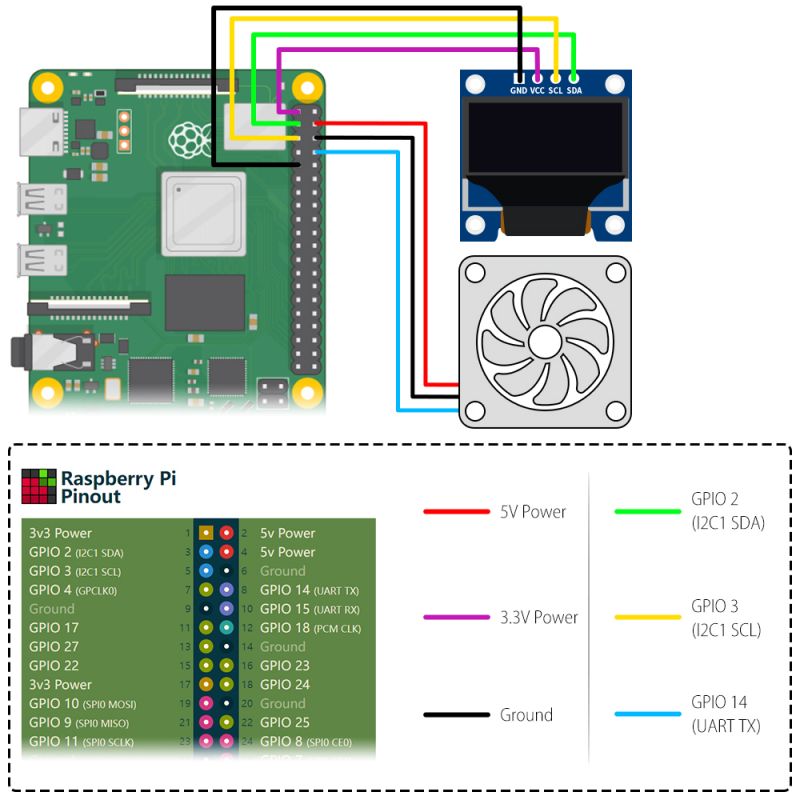
- 6. Fix 0.96 inch OLED display to the case with glue gun or tape, and connect the pins to GPIO according to the wiki's circuit diagram.
- 7. Fix two side with acrylic panel with screws.
- 8. You can also fix the fan to the arcrylic panel on the side.
Wiring Details
How to enable OLED screen
Method 1
0.96 inch OLED usage please refer to: [ https://wiki.52pi.com/index.php/S-0005 ] After installing ssd1306 driver, you can refer to the example code to create your own python script to show system informations.
Method 2
- This method will refer to Adafruit python SSD1306 example for this display.
Open a terminal and Download demo code from: [ https://github.com/adafruit/Adafruit_Python_SSD1306 ]
sudo python3 -m pip install --upgrade pip setuptools wheel
git clone https://github.com/adafruit/Adafruit_Python_SSD1306.git
cd Adafruit_Python_SSD1306
sudo python setup.py install
pip3 install Adafruit-BBIO
- Run example Demo:
cd examples/
- You may need to modify the stats.py as following code:
import time

import Adafruit_GPIO.SPI as SPI
import Adafruit_SSD1306

from PIL import Image
from PIL import ImageDraw
from PIL import ImageFont

import subprocess
import smbus2
# from ina219 import INA219, DeviceRangeError

# Raspberry Pi pin configuration:
RST = None     # on the PiOLED this pin isnt used
# Note the following are only used with SPI:
DC = 23
SPI_PORT = 0
SPI_DEVICE = 0
DEVICE_BUS = 1

DEVICE_ADDR  = 0x17
PROTECT_VOLT = 3700
SAMPLE_TIME = 2

ina_supply = INA219(0.00725, address=0x40)
ina_supply.configure()
supply_voltage = ina_supply.voltage()
supply_current = ina_supply.current()
supply_power = ina_supply.power()

ina_batt = INA219(0.005, address=0x45)
ina_batt.configure()
batt_voltage = ina_batt.voltage()
batt_current = ina_batt.current()
batt_power = ina_batt.power()


# Beaglebone Black pin configuration:
# RST = 'P9_12'
# Note the following are only used with SPI:
# DC = 'P9_15'
# SPI_PORT = 1
# SPI_DEVICE = 0

# 128x32 display with hardware I2C:
# disp = Adafruit_SSD1306.SSD1306_128_32(rst=RST)   ####### please comment this line by adding hash tag in front of line #######

# 128x64 display with hardware I2C:  ##########################Please Open following line by removing hash tag ######
disp = Adafruit_SSD1306.SSD1306_128_64(rst=RST)

# Note you can change the I2C address by passing an i2c_address parameter like:
# disp = Adafruit_SSD1306.SSD1306_128_64(rst=RST, i2c_address=0x3C)

# Alternatively you can specify an explicit I2C bus number, for example
# with the 128x32 display you would use:
# disp = Adafruit_SSD1306.SSD1306_128_32(rst=RST, i2c_bus=2)

# 128x32 display with hardware SPI:
# disp = Adafruit_SSD1306.SSD1306_128_32(rst=RST, dc=DC, spi=SPI.SpiDev(SPI_PORT, SPI_DEVICE, max_speed_hz=8000000))

# 128x64 display with hardware SPI:
# disp = Adafruit_SSD1306.SSD1306_128_64(rst=RST, dc=DC, spi=SPI.SpiDev(SPI_PORT, SPI_DEVICE, max_speed_hz=8000000))

# Alternatively you can specify a software SPI implementation by providing
# digital GPIO pin numbers for all the required display pins.  For example
# on a Raspberry Pi with the 128x32 display you might use:
# disp = Adafruit_SSD1306.SSD1306_128_32(rst=RST, dc=DC, sclk=18, din=25, cs=22)

# Initialize library.
disp.begin()

# Clear display.
disp.clear()
disp.display()

# Create blank image for drawing.
# Make sure to create image with mode '1' for 1-bit color.
width = disp.width
height = disp.height
image = Image.new('1', (width, height))

# Get drawing object to draw on image.
draw = ImageDraw.Draw(image)

# Draw a black filled box to clear the image.
draw.rectangle((0,0,width,height), outline=0, fill=0)

# Draw some shapes.
# First define some constants to allow easy resizing of shapes.
padding = -2
top = padding
bottom = height-padding
# Move left to right keeping track of the current x position for drawing shapes.
x = 0


# Load default font.
font = ImageFont.load_default()

# Alternatively load a TTF font.  Make sure the .ttf font file is in the same directory as the python script!
# Some other nice fonts to try: http://www.dafont.com/bitmap.php
# font = ImageFont.truetype('Minecraftia.ttf', 8)


# i2c bus configure
bus = smbus2.SMBus(DEVICE_BUS)
aReceivedBuf = []
aReceivedBuf.append(0x00)

for i in range(1, 255):
    aReceivedBuf.append(bus.read_byte_data(DEVICE_ADDR, i))

while True:

    # Draw a black filled box to clear the image.
    draw.rectangle((0,0,width,height), outline=0, fill=0)

    # Shell scripts for system monitoring from here : https://unix.stackexchange.com/questions/119126/command-to-display-memory-usage-disk-usage-and-cpu-load
    cmd = "hostname -I | cut -d\' \' -f1"
    IP = subprocess.check_output(cmd, shell = True )
    cmd = "top -bn1 | grep load | awk '{printf \"CPU Load: %.2f\", $(NF-2)}'"
    CPU = subprocess.check_output(cmd, shell = True )
    cmd = "free -m | awk 'NR==2{printf \"Mem: %s/%sMB %.2f%%\", $3,$2,$3*100/$2 }'"
    MemUsage = subprocess.check_output(cmd, shell = True )
    cmd = "df -h | awk '$NF==\"/\"{printf \"Disk: %d/%dGB %s\", $3,$2,$5}'"
    Disk = subprocess.check_output(cmd, shell = True )

    aReceivedBuf = []
    aReceivedBuf.append(0x00)

    for i in range(1, 255):
        aReceivedBuf.append(bus.read_byte_data(DEVICE_ADDR, i))

    batt_voltage = ina_batt.voltage()
    batt_current = ina_batt.current()
    batt_power = ina_batt.power()
    if (aReceivedBuf[8] << 8 | aReceivedBuf[7]) > 4000:
        charge_port = 'Charging via Type-C'
    elif (aReceivedBuf[10] << 8 | aReceivedBuf[9]) > 4000:
        charge_port = 'Charging via MicroUSB'
    else:
        charge_port = 'Not Charging'

    # Write two lines of text.

    draw.text((x, top),       "IP: " + str(IP.decode('utf-8')),  font=font, fill=255)
    draw.text((x, top+8),     str(CPU.decode('utf-8')), font=font, fill=255)
    draw.text((x, top+16),    str(MemUsage.decode('utf-8')),  font=font, fill=255)
    draw.text((x, top+25),    str(Disk.decode('utf-8')),  font=font, fill=255)

    # Display image.
    disp.image(image)
    disp.display()
    time.sleep(3)

    draw.rectangle((0,0,width,height), outline=0, fill=0)
    draw.text((x, top),"Voltage: " + str(batt_voltage),  font=font, fill=255)
    draw.text((x, top+8), "Current:" + str(batt_current), font=font, fill=255)
    draw.text((x, top+16),"Power:" + str(batt_power),  font=font, fill=255)
    draw.text((x, top+25),"ChargePort:" + str(charge_port),  font=font, fill=255)
    # display UPS information

    disp.image(image)
    disp.display()
    time.sleep(3)
- Then execute following command:
python3 stats.py
Method 3
- Easy way
1. Turn on `i2c function` by using `sudo raspi-config` -> `interface options` -> `i2c` -> `enable` -> `yes`.
2. Check if the screen has been recognized by Raspberry Pi.
i2cdetect -y 1
if encount `command not found` error, please install `i2c-tools` by using `sudo apt update && sudo apt -y install i2c-tools`.
3. Install dependencies libraries:
sudo apt -y install python3 python3-pip python3-pil libjpeg-dev zlib1g-dev libfreetype6-dev liblcms2-dev libopenjp2-7 libtiff5
4. Grant privilleges to user `pi`
sudo usermod -a -G gpio,i2c pi
5. Download sample code from this repo:
git clone https://github.com/rm-hull/luma.examples.git
cd luma.examples/
6. Install the dependencies
sudo -H pip3 install -e .
7. Entering into example folder and test it.
cd luma.examples/examples/
python3 sys_info.py
OLED Configuration Tutorial Video
- YouTube channel: [ https://youtu.be/AxBXI-b07lc ]
Documentations
- SSD1306 Datasheet:File:SSD1306-Revision 1.0.pdf
- Mechanical Drawing:File:0.96inch Mechanical Drawing.pdf
- UPS Plus: [ https://wiki.52pi.com/index.php/UPS_Plus_SKU:_EP-0136 ]
- Github: [ https://github.com/geeekpi/minitowercase/edit/main/README.md ]
How to display UPS information on OLED
- 1.Make sure OLED display has been connected to Raspberry Pi on GPIO properly.
check if the OLED screen is detected by Raspberry Pi via using following command in terminal: `i2cdetect -y 1`
- 2.Enable `I2C function` by using `sudo raspi-config` command, and navigate to `interface options` -> `I2C` -> `Enable` -> `YES`.
- 3.Make sure Raspberry Pi has been connected to internet.
- 4.Install dependents package via following commands:
sudo usermod -a -G i2c,spi,gpio pi
sudo apt install python-dev python-pip libfreetype6-dev libjpeg-dev build-essential
sudo apt install libsdl-dev libportmidi-dev libsdl-ttf2.0-dev libsdl-mixer1.2-dev libsdl-image1.2-dev
sudo -H pip3 install psutil
sudo -H pip3 install pi-ina219
sudo -H pip3 install Pillow
- Log out and in again and clone this repository:
git clone https://github.com/rm-hull/luma.examples.git
cd luma.examples
- Finally, install the luma libraries using:
sudo -H pip3 install -e .
- Change directory to `luma.examples/examples`
cd luma.examples/examples/
- Backup `sys_info.py` file.
cp sys_info.py sys_info.py.bak
If UPS Plus is Connected
- Modify `sys_info.py` file as following code, this is just a demo code, you can modify it as you want:
import os
import sys
import time
from pathlib import Path
from datetime import datetime
import smbus2
from ina219 import INA219, DeviceRangeError

if os.name != 'posix':
    sys.exit('{} platform not supported'.format(os.name))

from demo_opts import get_device
from luma.core.render import canvas
from PIL import ImageFont

try:
    import psutil
except ImportError:
    print("The psutil library was not found. Run 'sudo -H pip install psutil' to install it.")
    sys.exit()

# setting up configuration of UPS device.
DEVICE_BUS = 1
DEVICE_ADDR = 0x17
PROTECT_VOLT = 3700
SAMPLE_TIME = 2

# initializing an instance of ina_supply.
ina_supply = INA219(0.00725, address=0x40)
ina_supply.configure()
supply_voltage = ina_supply.voltage()
supply_current = ina_supply.current()
supply_power = ina_supply.power()

# initializing instance of batteries status.
ina_batt = INA219(0.005, address=0x45)
ina_batt.configure()
batt_voltage = ina_batt.voltage()
batt_current = ina_batt.current()
batt_power = ina_batt.power()

# initializing an I2C bus.
bus = smbus2.SMBus(DEVICE_BUS)

# functions
def bytes2human(n):
    """
    >>> bytes2human(10000)
    '9K'
    >>> bytes2human(100001221)
    '95M'
    """
    symbols = ('K', 'M', 'G', 'T', 'P', 'E', 'Z', 'Y')
    prefix = {}
    for i, s in enumerate(symbols):
        prefix[s] = 1 << (i + 1) * 10
    for s in reversed(symbols):
        if n >= prefix[s]:
            value = int(float(n) / prefix[s])
            return '%s%s' % (value, s)
    return "%sB" % n

# display cpu usage.
def cpu_usage():
    # load average, uptime
    uptime = datetime.now() - datetime.fromtimestamp(psutil.boot_time())
    av1, av2, av3 = os.getloadavg()
    return "Ld:%.1f %.1f %.1f Up: %s" \
        % (av1, av2, av3, str(uptime).split('.')[0])

# display memory usage.
def mem_usage():
    usage = psutil.virtual_memory()
    return "Mem: %s %.0f%%" \
        % (bytes2human(usage.used), 100 - usage.percent)

# display disk usage.
def disk_usage(dir):
    usage = psutil.disk_usage(dir)
    return "SD:  %s %.0f%%" \
        % (bytes2human(usage.used), usage.percent)

# display network status.
def network(iface):
    stat = psutil.net_io_counters(pernic=True)[iface]
    return "%s: Tx%s, Rx%s" % \
           (iface, bytes2human(stat.bytes_sent), bytes2human(stat.bytes_recv))

# draw status on OLED screen.
def stats(device):
    # use custom font
    font_path = str(Path(__file__).resolve().parent.joinpath('fonts', 'C&C Red Alert [INET].ttf'))
    font2 = ImageFont.truetype(font_path, 12)

    with canvas(device) as draw:
        draw.text((0, 0), cpu_usage(), font=font2, fill="white")
        if device.height >= 32:
            draw.text((0, 14), mem_usage(), font=font2, fill="white")

        if device.height >= 64:
            draw.text((0, 26), disk_usage('/'), font=font2, fill="white")
            try:
                draw.text((0, 38), network('wlan0'), font=font2, fill="white")
            except KeyError:
                # no wifi enabled/available
                pass

# display charging port status.
def chrg_port():
    aReceivedBuf = []
    aReceivedBuf.append(0x00)
    for i in range(1, 255):
        aReceivedBuf.append(bus.read_byte_data(DEVICE_ADDR, i))

    if (aReceivedBuf[8] << 8 | aReceivedBuf[7]) > 4000:
        charge_port = 'Charging via TYPE-C'
    elif (aReceivedBuf[10] << 8 | aReceivedBuf[9]) > 4000:
        charge_port = 'Charging via MicroUSB'
    else:
        charge_port = 'Not Charging'
    return "CP: %s" % charge_port

# display batteries current status.
def batt_cur():
    aReceivedBuf = []
    aReceivedBuf.append(0x00)
    for i in range(1, 255):
        aReceivedBuf.append(bus.read_byte_data(DEVICE_ADDR, i))
    chrg_rate = ina_batt.current()
    return "Bat Current: %.3f mA" % chrg_rate

# display batteries capacity status.
def batt_cap():
    aReceivedBuf = []
    aReceivedBuf.append(0x00)
    for i in range(1, 255):
        aReceivedBuf.append(bus.read_byte_data(DEVICE_ADDR, i))
    capacity = (aReceivedBuf[20] << 8 | aReceivedBuf[19])
    return "Bat Capacity: %d%%"% capacity

# display full batteries voltage status.
def full_bat():
    aReceivedBuf = []
    aReceivedBuf.append(0x00)
    for i in range(1, 255):
        aReceivedBuf.append(bus.read_byte_data(DEVICE_ADDR, i))
    full_batt = (aReceivedBuf[14] << 8 | aReceivedBuf[13])
    return "Full Bat Voltage: %d mV" % full_batt

# display UPS status infor on OLED screen.
def ups_status(device):
    # use custom font
    font_path = str(Path(__file__).resolve().parent.joinpath('fonts', 'C&C Red Alert [INET].ttf'))
    font2 = ImageFont.truetype(font_path, 12)

    with canvas(device) as draw:
        draw.text((0, 0), full_bat(), font=font2, fill="white")
        if device.height >= 32:
            draw.text((0, 14), batt_cap(), font=font2, fill="white")

        if device.height >= 64:
            draw.text((0, 26), chrg_port(), font=font2, fill="white")
            try:
                draw.text((0, 38), batt_cur(), font=font2, fill="white")
            except KeyError:
                # no wifi enabled/available
                pass

# define mainloop.
def main():
    while True:
        stats(device)
        time.sleep(5)
        ups_status(device)
        time.sleep(5)

if __name__ == "__main__":
    try:
        device = get_device()
        main()
    except KeyboardInterrupt:
        pass
- Execute it.
python3 sys_info.py
Keywords
- Mini Tower UPS Kit, UPS case, ice tower case, case for raspberry pi 4B.
