K-0502
ABS Holder Kit for RPi & Arduino
Description
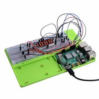
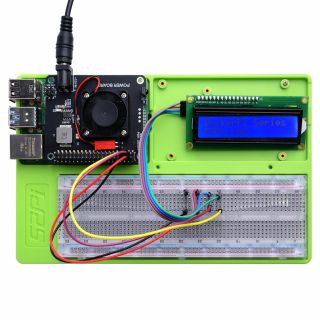
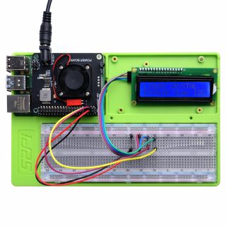
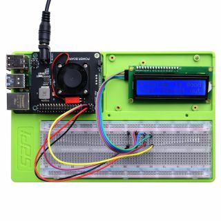
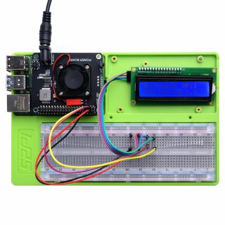
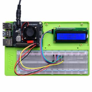
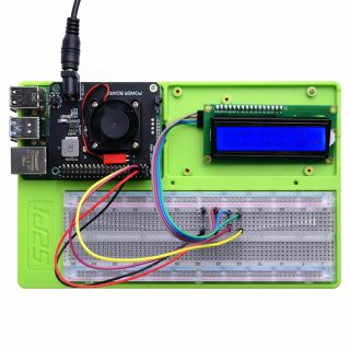
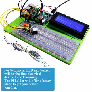
This is a Raspberry Pi experimental tray kit for raspberry beginners or Arduino beginners.
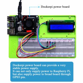
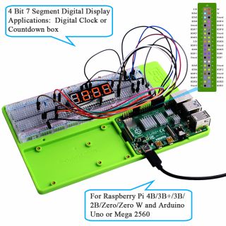
It contains a long breadboard and a breadboard power supply that provides 3.3v and 5v power to the breadboard power rails.
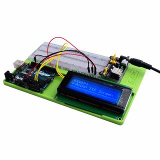
It is easy to deploy electronic components and the Raspberry Pi or Arduino development board can be fixed on the tray.
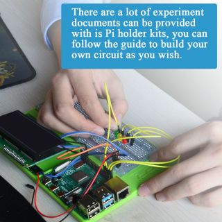
It is convenient to carry out and can protect the device well, prevent short circuit and so on.
It can also prevent the jump wire from loosening during the movement.
Fit for circuit experiments with Raspberry Pi and Arduino Uno/Mega 2560.
Features
- Easy to assemble
- ABS Material with screw holes
- Long breadboard
- Starter kits for the electronic experiments
- Compatibles with Raspberry Pi and Arduino Uno/mega 2560
- Breadboard power supply (Offer 3.3V and 5V)
- Two Colors: Blue & Green
Gallery
Package Includes
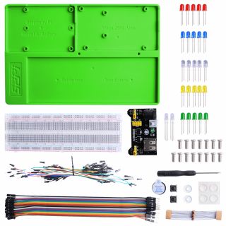
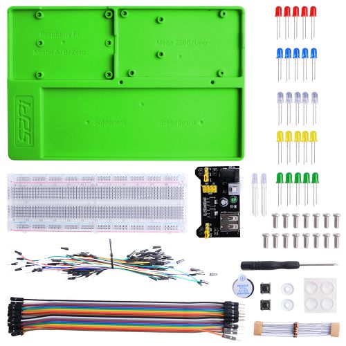
- 1 x ABS Holder Kit For RPi & Arduino(experimental tray kit)
- 1 x Long breadboard
- 1 x Breadboard power supply(6.5-12V DC Input,5V/3.3V Output)
- 5 x Red LED
- 5 x Blue LED
- 5 x White LED
- 5 x Yellow LED
- 5 x Green LED
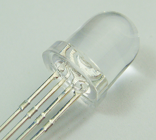
- 2 x RGB LED
- 2 x Button
- 1 x Buzzer
- 10 x 1KΩ Resister
- 2 x Acrylic washer
- 40 x Male-to-Female jump wire
- 40 x Male-to-Male jump wire
- 15 x Screw
- 1 x Anti-slipper pad
- 1 x Screw driver
Applications
Documentations
Lesson 1 Blinking LED
- Steps:
- 1. Download the latest image file(Raspbian) from: https://www.raspberrypi.org/downloads/
- 2. Unzip it and flash it to TF card by using Etcher tool or win32_diskimager tool.
- 3. Remove old version of wiringPi software and download and install the latest wiringPi software:
sudo apt -y purge wiringpi
hash -r
cd /tmp
wget https://project-downloads.drogon.net/wiringpi-latest.deb
sudo dpkg -i wiringpi-latest.deb
gpio readall
gpio -v
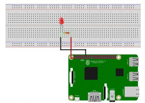
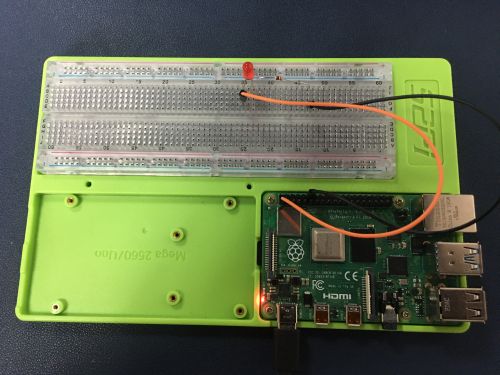
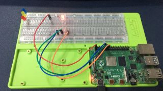
- 4. Connect LED and 220Ω Resister to breadboard and connect LED to Raspberry Pi's GPIO on Pin number 12 as following picture:
- 5. Create a file with code as following:
- Programming in Language C:
- 5. Create a file with code as following:
Create a file named led.c and paste following code:
#include <stdio.h>
#include <wiringPi.h>

//define the led macro value.  1 means wiringPi name style, you should connect led positive pin to physical pin 12.
int LED = 1;
// main function
int main(void)
{
        // initialized environment
        // infinity loops
        wiringPiSetup();
        pinMode(LED, OUTPUT);
//Loops
        for(;;)
        {
                digitalWrite(LED,HIGH);  //Turn on led
                delay(20);
                digitalWrite(LED,LOW);   //Turn off led
                delay(20);
        }
        return 0;
}
Compile and run it:
gcc -o led  -lwiringPi led.c
./led
- Programming in Python:
1.Install RPi.GPIO:
pip3 install RPi.GPIO
2. Create a file named blink_led.py and paste following code:
#!/usr/bin/env python3
import RPi.GPIO as GPIO    # Import Raspberry Pi GPIO library
from time import sleep     # Import the sleep function from the time module

LED = 18 # Define led pin's name (BCM naming style)
GPIO.setwarnings(False)    # Ignore warning for now
GPIO.setmode(GPIO.BCM)   # Use physical pin numbering
GPIO.setup(LED, GPIO.OUT, initial=GPIO.LOW)   # Set pin 18 to be an output pin and set initial value to low (off)

while True: # Run forever
    GPIO.output(LED, GPIO.HIGH) # Turn on
    sleep(1)                  # Sleep for 1 second
    GPIO.output(LED, GPIO.LOW)  # Turn off
    sleep(1)                  # Sleep for 1 second
3.Run the code:
python3 blink_led.py
Lesson 2 RGB LED Shifting
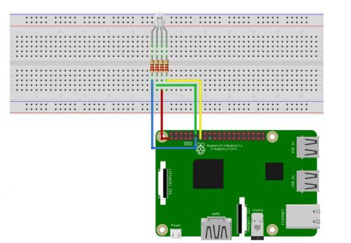
- Component and pin definitions
- Connection Details
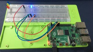
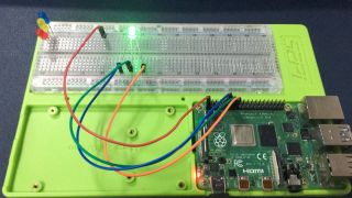
- Demo status
- Demo code
// header files
#include <stdio.h>
#include <wiringPi.h>

int LED[3]= {0,1,2};  // define an array to store leds pin, 0 - blue led, 1 - green led, 2 - red led.
int x = 200;      // interval for the delay.

int main(void)
{
        wiringPiSetup();   //initialized wiringPi.
        for(int i=0; i<3; i++)
        {
                pinMode(LED[i], OUTPUT);      // set direction of the LED pin to output.
                digitalWrite(LED[i], HIGH);   // turn off all leds.
        }
        for(;;)
        {
                for(int i=0; i<3; i++)
                {
                        if(i==0)
                        {
                        digitalWrite(LED[i],LOW);    //turn on blue led
                        digitalWrite(LED[i+1],HIGH); //turn off green led
                        digitalWrite(LED[i+2],HIGH); //turn off red led
                        delay(x);
                        }
                        if(i==1)
                        {
                        digitalWrite(LED[i],LOW);   //turn on green led
                        digitalWrite(LED[i-1],HIGH); //turn off blue led
                        digitalWrite(LED[i+1],HIGH);  //turn off red led
                        delay(x);
                        }
                        if(i==2)
                        {
                        digitalWrite(LED[i],LOW);     //turn on red led
                        digitalWrite(LED[i-1],HIGH);  //turn off green led
                        digitalWrite(LED[i-2],HIGH);  //turn off blue led
                        delay(x);
                        }
                }
        }
        return 0;
}
- Compile the code with gcc tool and run:
gcc -o rgbled -lwiringPi rgbled.c
./rgbled
Lesson 3 Buzzer
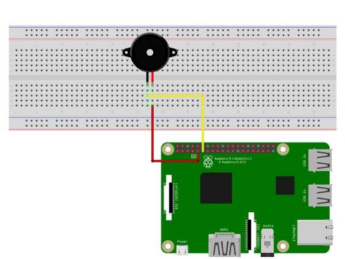
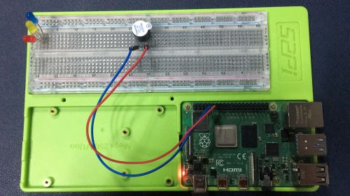
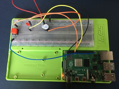
- Build circuit
- Connect the long pin of the buzzer to 3V3 pin on Raspberry Pi and short pin to GPIO.2
- Demo code
#include <stdio.h>
#include <wiringPi.h>

#define buzzer 0   // gpio.0 Equal BCM Pin 17
int interval = 0;

int main(void)
{
        wiringPiSetup();
        pinMode(buzzer, OUTPUT);
        digitalWrite(buzzer, LOW);
        for(;;)
        {
                for(interval=0; interval<=50; interval+=2)
                {
                digitalWrite(buzzer,HIGH);
                delay(interval);
                digitalWrite(buzzer,LOW);
                delay(interval);
                }
                for(interval=50; interval>=0; interval-=2)
                {
                digitalWrite(buzzer,HIGH);
                delay(interval);
                digitalWrite(buzzer,LOW);
                delay(interval);
                }
        }
        return 0;
}
- Compile it and run:
gcc -o buzzer -lwiringPi buzzer.c
./buzzer
Lesson 4 Morse Code
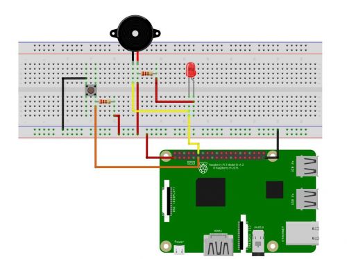
Morse code device will help childs to learn morse code:
- Build circuit
- Write the code
#include <stdio.h>
#include <wiringPi.h>

#define LED 1
#define BUTTON 0
int x = 200;

int main(void)
{
        wiringPiSetup();    //initialized
        pinMode(LED, OUTPUT);   // set direction of the led pin.
        digitalWrite(LED, LOW);  // turn off led
        pinMode(BUTTON, INPUT);  // set direction of button pin as input pin
        for(;;)
        {
                if(digitalRead(BUTTON) == 0)    // read Button's status
                {
                   delay(15);      // bounce time
                   if(digitalRead(BUTTON) == 0)
                   {
                        digitalWrite(LED,LOW);    // led pin's status will turn on the buzzer and led.
                   }
                   else
                   {
                        digitalWrite(LED,HIGH);   // turn off.
                   }
                 }
        }
        return 0;
}
- Compile and run it
gcc -o morsecode  -lwiringPi morsecde.c
./morsecode
Lesson 5 Button Control
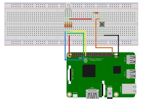
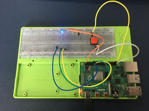
This lesson will show you how to control each LED of a RGB LED by using a push button.
- Build Circuit
- Write code
#include <stdio.h>
#include <wiringPi.h>

#define button 29
int LED[3]= {0,1,2};
int x = 200;
int press_times = 0;

int main(void)
{
        wiringPiSetup();
        for(int i=0; i<3; i++)
        {
                pinMode(LED[i], OUTPUT);
                digitalWrite(LED[i], HIGH);
                pinMode(button, INPUT);
        }
        for(;;)
        {
                if(digitalRead(button) == 0)
                {
                        delay(15);
                        if(digitalRead(button) == 0)
                        {
                                if(press_times > 3)
                                {
                                        press_times = 0;
                                }
                        }
                        switch(press_times)
                        {
                                case 1:
                                {
                                        printf("Press 1 time, turn on blue led.\n");
                                        digitalWrite(LED[0],LOW);
                                        digitalWrite(LED[1],HIGH);
                                        digitalWrite(LED[2],HIGH);
                                        delay(x);
                                        break;
                                }
                                case 2:
                                {
                                        printf("Press 2 times, turn on green led.\n");
                                        digitalWrite(LED[0],HIGH);
                                        digitalWrite(LED[1],LOW);
                                        digitalWrite(LED[2],HIGH);
                                        delay(x);
                                        break;
                                }
                                case 3:
                                {
                                        printf("Press 1 time, turn on red led.\n");
                                        digitalWrite(LED[0],HIGH);
                                        digitalWrite(LED[1],HIGH);
                                        digitalWrite(LED[2],LOW);
                                        delay(x);
                                        break;
                                }

                        }
                        press_times++;
                }
        }
        return 0;
}
- Compile and run it.
gcc -o buttoncontrol -lwiringPi buttoncontrol.c
./buttoncontrol
and then you will see the color change if you press button.
