EZ-0062
GeeekNET ESP32 Development Board
Description
GeeekNET ESP32 Development Board is made with the official WROOM32 module.
There is built in USB-to-Serial converter, automatic bootloader reset, Lithium Ion/Polymer charger.
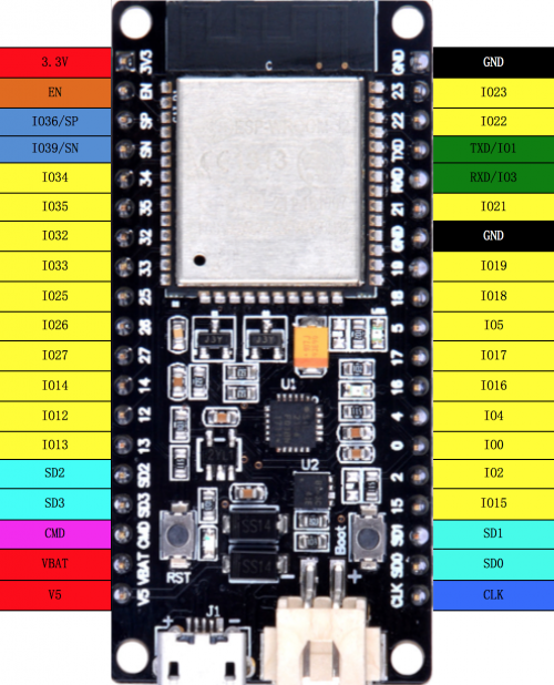
And just about all of the GPIOs brought out so you can use it with any sensor.
That module contains a dual-core ESP32 chip, 4 MB of SPI Flash, tuned antenna.
And all the passives you need to take advantage of this powerful new processor.
The ESP32 has both WiFi and Bluetooth Classic/LE support.
That means it's perfect for just about any wireless or Internet-connected project.
The ESP32 is a perfect upgrade from the ESP8266 that has been so popular.
In comparison, the ESP32 has way more GPIO, plenty of analog inputs,
two analog outputs, multiple extra peripherals (like a spare UART),
two cores so you don't have to yield to the WiFi manager, much higher-speed processor, etc.
Please note: The ESP32 is still targeted to developers.
Not all of the peripherals are fully documented with example code, and there are some bugs still being found and fixed.
We got it working under Arduino IDE, so you can expect things like I2C and SPI and analog reads to work.
And also we got it working under MicroPython, so you can test it with the command line console, it will be nice to programmer.
But other elements are still under development.
For that reason, we recommend this module for makers who have some experience with microcontroller programming, and not as a first dev board.
Galley
Product Details
- Voltage: 5V
- Current: 80mA
- Battery: 3.7V
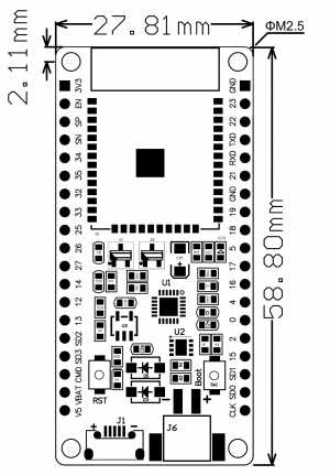
- Dimension: 59.76mmx28.05mmx12.60mm
- Weight: 9.75g ±0.5
ESP32 module Specifications
| WiFi | Bluetooth | CPU and Memory | Clocks and Timers | Advanced Peripheral Interfaces | Security | Cryptographic hardware acceleration | Development Support |
|---|---|---|---|---|---|---|---|
|
|
|
|
|
|
|
|
Mechanical Drawing
- Download PDF file:
GeeeKNET ESP32 Development Board Pin Layout
Package Include
1 x GeeekNET ESP32 Development Board
Applications
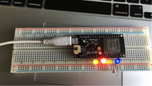
Most people lights up LEDs at the very beginning when they got this module.
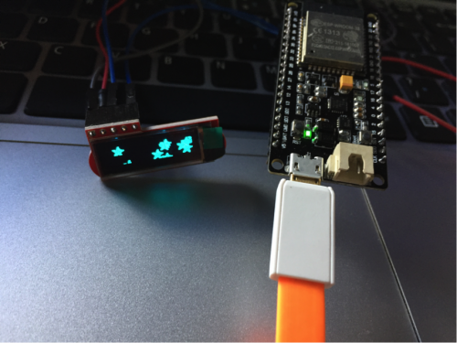
And you can also drive 0.91inch OLED by adafruit driver in Arduino IDE:
Working on Arduino IDE
- Installation instructions for Windows
- Installation instructions for Debian / Ubuntu OS
1. Install latest Arduino IDE from [arduino.cc]
Open Terminal and execute the following command (copy->paste and hit enter):
sudo usermod -a -G dialout $USER && \
sudo apt-get install git && \
wget https://bootstrap.pypa.io/get-pip.py && \
sudo python get-pip.py && \
sudo pip install pyserial && \
mkdir -p ~/Arduino/hardware/espressif && \
cd ~/Arduino/hardware/espressif && \
git clone https://github.com/espressif/arduino-esp32.git esp32 && \
cd esp32/tools/ && \
python get.py
2. Restart Arduino IDE
- Installation instructions for Mac OS
1. Install latest Arduino IDE from [arduino.cc]
Open Terminal and execute the following command (copy->paste and hit enter):
mkdir -p ~/Documents/Arduino/hardware/espressif && \
cd ~/Documents/Arduino/hardware/espressif && \
git clone https://github.com/espressif/arduino-esp32.git esp32 && \
cd esp32/tools/ && \
python get.py
- Restart Arduino IDE
Working on MicroPython
- You can download the latest firmware for ESP32 boards:
Download Firmware for ESP32 boards
- The following files are daily firmware for ESP32-based boards. (Unzip it before using it)
Download Old version Esp32-20170822-v1.9.1-438-g392aaffc.bin.zip
Program your board using the esptool.py program, and put the firmware starting at address 0x1000
If you are putting MicroPython on for the first time then you should first erase the entire flash.
PS: /dev/ttyUSB1 may different on your PC, please make sure it correctly.
sudo esptool.py --chip esp32 --port /dev/ttyUSB1 erase_flash
sudo esptool.py --chip esp32 --port /dev/ttyUSB1 write_flash -z 0x1000 firmware.bin)
After that, you need install esptool.py and a software called "picocom" in your Linux system( debain, ubuntu, or raspbian):
There are a lot of terminal softwares such as "minicom" or "screen". You can select one of them by yourself.
sudo pip install esptool.py
sudo apt-get -y install picocom
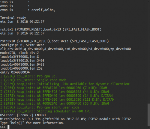
sudo picocom -b 115200 /dev/ttyUSB1
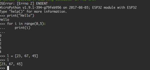
You will enter an IDE environment so you can coding by python language.
eg. you can import machine module as:
import machine
- Or just test range function it in your IDE:
- Control LED Pin
 from machine import Pin

p0 = Pin(0, Pin.OUT)    # Setting GPIO0's direction to output mode

p0.value(1)             # Setting values to 1 means "HIGH" level

p0.value(0)             # Setting values to 0 means "LOW" level
Machine module
You can using the Machine module to read CPU frequency.
import machine

machine.freq()                         # get current CPU frequency

machine.freq(160000000)     # set current CPU frequency
ESP-IDF SDK
- Obtaining v2.1
The source files attached to this release will not work due to our use of git submodules. Use one of the following methods instead:
- Using git
To get this release, use the following commands:
git clone https://github.com/espressif/esp-idf.git esp-idf-v2.1
cd esp-idf-v2.1/
git checkout v2.1
git submodule update --init --recursive
This is the recommended way of obtaining v2.1 of ESP-IDF.
FAQ
When I tested this Modul, there is an Error-Message when it starts up:
rst:0x1 (POWERON_RESET),boot:0x13 (SPI_FAST_FLASH_BOOT)
flash read err, 1000
Falling back to built-in command interpreter.
OK

It looks like the Flash-Memory in the this Modul has too slow StartUp-Time
for the ESP32 ?

Can you help ?
- It's due to without any program download into the ESP32 module, you can edit the example program and upload it by arduino IDE or esptool.py tool.
More Information
- [ The internet of things | http://esp32.net/ ]


