EZ-0061
ESP32 WROVER
Description
ESP32-WROVER is a powerful, generic WiFi-BT-BLE MCU module that targets a wide variety of applications,
ranging from low-power sensor networks to the most demanding tasks, such as voice encoding, music streaming and MP3 decoding.
At the core of this module is the ESP32-D0WDQ6 chip*, same as ESP-WROOM-32 module.
Compared to ESPWROOM-32, ESP32-WROVER has an additional SPI Pseudo static RAM (PSRAM) of 32 Mbits.
As such, ESP32- WROVER features both 4 MB external SPI flash and 4 MB external PSRAM.
The ESP32-WROVER module has a PCB antenna, while the ESP32-WROVER-I uses an IPEX antenna.
The information in this datasheet is applicable to both of the two modules.
The chip embedded is designed to be scalable and adaptive.
There are two CPU cores that can be individually controlled, and the clock frequency is adjustable from 80 MHz to 240 MHz.
The user may also power off the CPU and make use of the low-power coprocessor to constantly monitor the peripherals for changes or crossing of thresholds.
ESP32 integrates a rich set of peripherals, ranging from capacitive touch sensors, Hall sensors, low-noise sense amplifiers,
SD card interface, Ethernet, high-speed SPI, UART, I2S and I2C.
The integration of Bluetooth, Bluetooth LE and Wi-Fi ensures that a wide range of applications can be targeted, and that the module is future proof:
- using Wi-Fi allows a large physical range and direct connection to the internet through a Wi-Fi router,
- while using Bluetooth allows the user to conveniently connect to the phone or broadcast low energy beacons for its detection.
- The sleep current of the ESP32 chip is less than 5 µA, making it suitable for battery powered and wearable electronics applications.
ESP32 supports a data rate of up to 150 Mbps, and 22 dBm output power at the antenna to ensure the widest physical range.
As such the chip does offer industry-leading specifications and the best performance for electronic integration, range, power consumption, and connectivity.
The operating system chosen for ESP32 is freeRTOS with LwIP; TLS 1.2 with hardware acceleration is built in as well.
Secure (encrypted) over the air (OTA) upgrade is also supported, so that developers can continually upgrade their products even after their release.
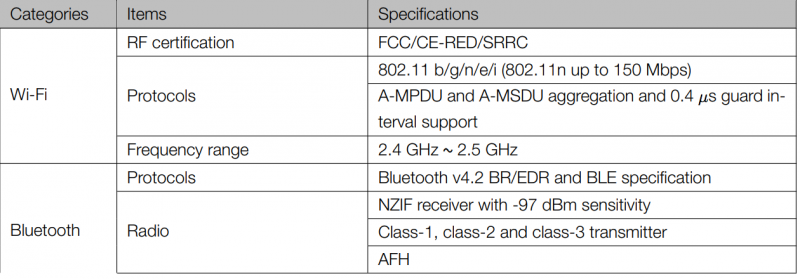
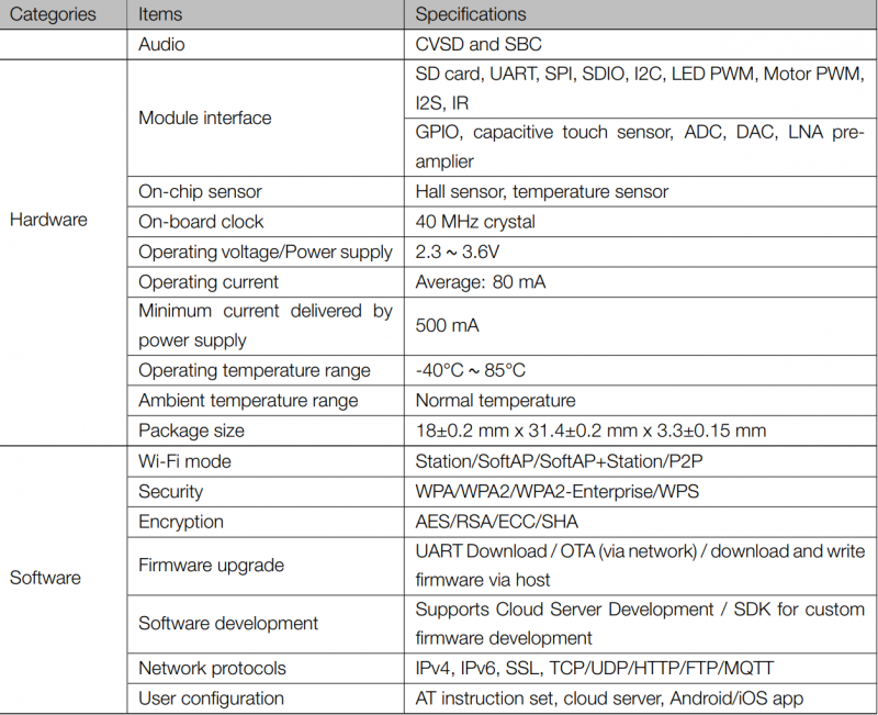
Specifications
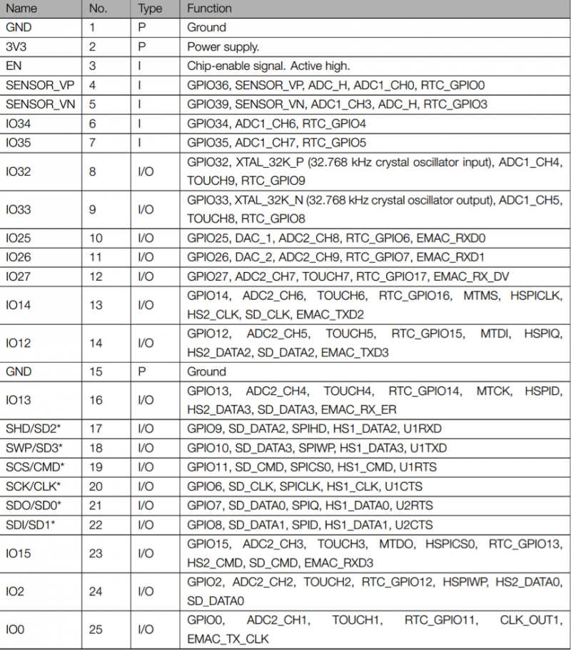
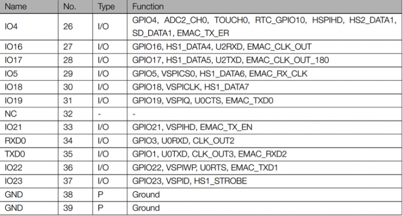
Pin definitions
- Pin Layout
Strapping Pins
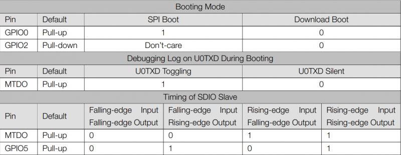
Please refer to Chapter 6 ESP32-WROVER schematics. ESP32 has five strapping pins:
- MTDI
- GPIO0
- GPIO2
- MTDO
- GPIO5
Software can read the value of these five bits from the register ”GPIO_STRAPPING”.
During the chip power-on reset, the latches of the strapping pins sample the voltage level as strapping bits of ”0”
or ”1”, and hold these bits until the chip is powered down or shut down. The strapping bits configure the device
boot mode, the operating voltage of VDD_SDIO and other system initial settings.
Each strapping pin is connected with its internal pull-up/pull-down during the chip reset. Consequently, if a strapping
pin is unconnected or the connected external circuit is high-impendence, the internal weak pull-up/pull-down
will determine the default input level of the strapping pins.
To change the strapping bit values, users can apply the external pull-down/pull-up resistances, or apply the host
MCU’s GPIOs to control the voltage level of these pins when powering on ESP32.
After reset, the strapping pins work as the normal functions pins.
Refer to Table 4 for detailed boot modes configuration by strapping pins.
