EP-0146
CM4 Router Board
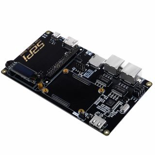
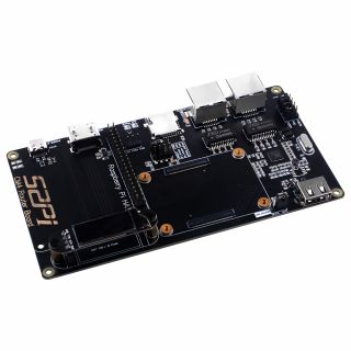
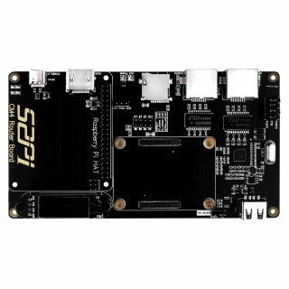
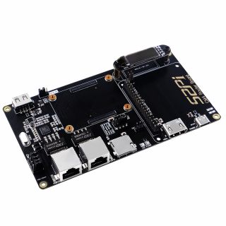
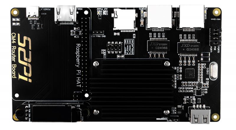
CM4 Router Board is an expansion board based on the Raspberry Pi Compute Module 4. It brings Raspberry Pi CM4 two full-speed gigabit network ports and offers better performance, lower CPU usage, and higher stability for a long time work compared with a USB network card.
The board still retains the characteristic GPIO pin header of Raspberry Pi, which makes it applicable for connecting other hat board such as Pi hats, sensors, and PoE hat board, and cooling fan, etc.
There is also a USB2.0 interface that can be connected to USB flash driver, USB keyboard, printers, WIFI modules,etc.
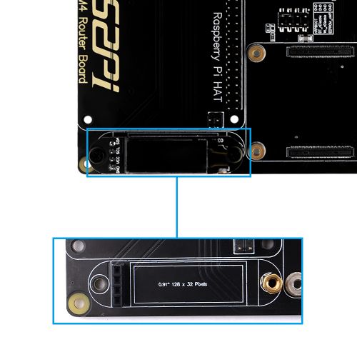
Besides, there is an OLED(0.91 inch) screen will help you to customize your Router Board's information display style.
It provides OpenWRT open-source router system. After a simple setup, it can be used as a router. It is also compatible with Raspberry OS, Ubuntu Server and other Raspberry Pi systems, even you can make this router board a retrogame machine at home.
The standard HDMI interface can help you configure the device and display operating information conveniently.
The powerful performance of BCM2711 4 core 1.5GHz Cortex-A72 and the rich software support in the Raspberry Pi community make this board a solid foundation for building high-performance gateways, smart routers, and home IoT platforms. It can also be connected to peripherals and used as a mini-NAS, wireless network bridge, or mini server which can be controlled via terminal.
If you need multiple LAN network ports like common routers, it is recommended to use a gigabit switch to expand the network ports, which will not affect its Internet performance.
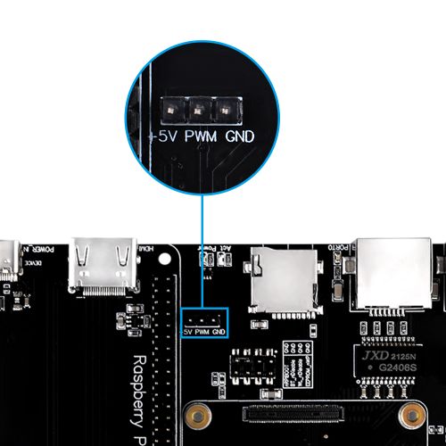
5V DC Fan interface supports 5V cooling fan, it can alse support PWM protocol, that means you can control the speed of fan blades via PWM signal. The 52Pi CM4 Router Board can be used as a router or other applications.
Features & Specifications
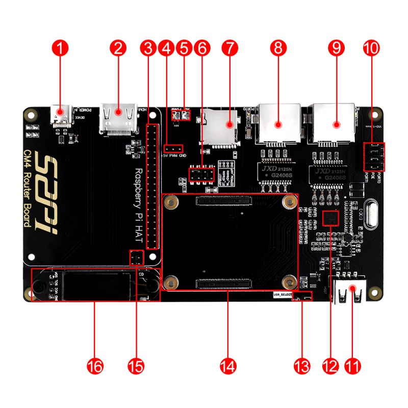
- Compatible Module: Raspberry Pi Compute Module 4 series
- Support standard Raspberry Pi HAT interface
- Support POE HAT to supply power to the board
- Support POE HAT for external power supply
- Full-speed dual gigabit network interface
- Master-slave dual USB2.0 interface
- Micro SD card slot, used to support non-eMMC version of CM4
- Standard HDIM video output interface
- 0.91 inch IIC OLED display
- 5V DC fan interface(Support controlling via PWM signal)
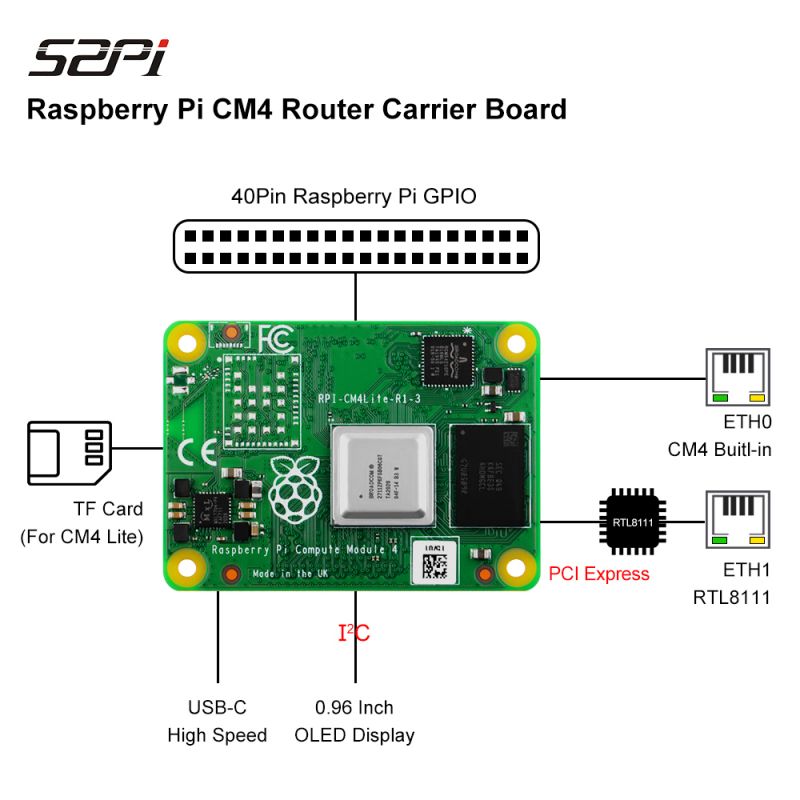
- Ethernet: high-performance Gigabit ethernet controller RTL8111E chip, JXD 2111x G2406s chip as isolation transformer.
- Port0: Compute Module 4 Built-In
- Port1: PCI Express 1000BASE-T NIC
- GPIO: 40Pin GPIO compatible with Raspberry Pi
- Power Supply: USB-C(Type-C) 5V/3A interface
- Operating Temperature: 0℃~80℃
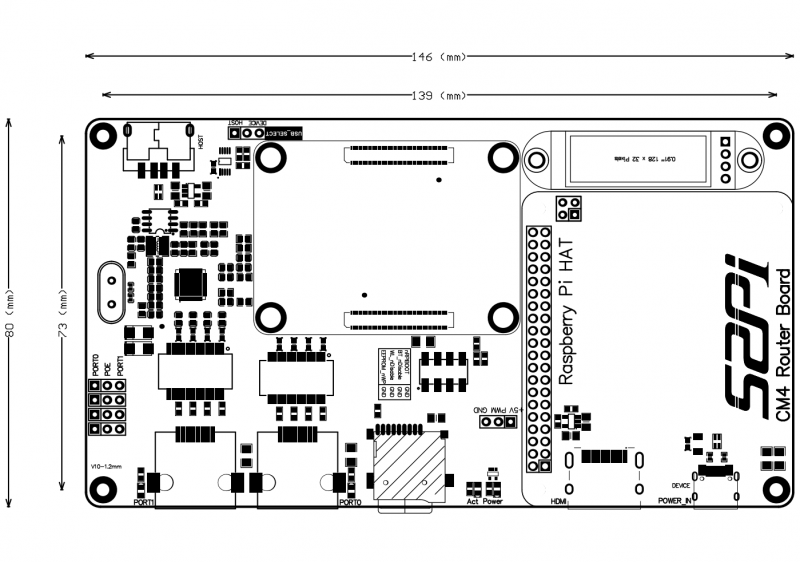
- Dimension: 146 x 80mm
Gallery
- Product Outlook
- Circuit Topology Concept
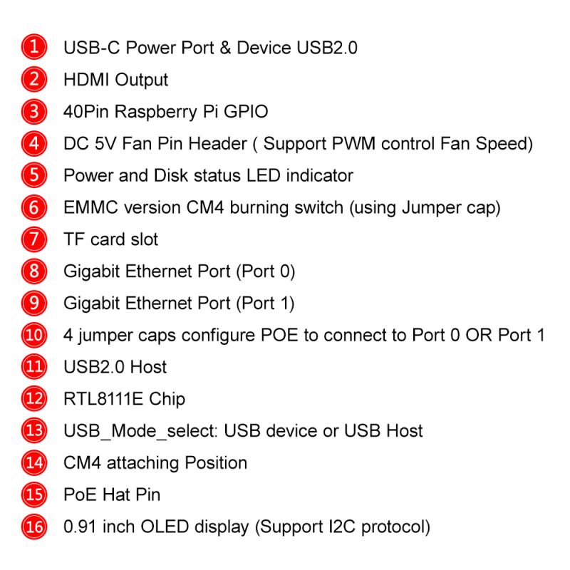
- Pin header Details
- Product Mechanical Drawing:
NOTE: The USB interface is disabled to save power by default on the CM4 . To enable it you need to add dtoverlay=dwc2,dr_mode=host to the config.txt file and reboot)
Description of Pin Header
DC 5V Fan Pin Header
Those Pins can be handled by Raspberry Pi OS itself or by programming, please refer to `raspi-config` tool.
| Silk Mark | Note |
|---|---|
| +5V | Connect to Positive Pin of Fan |
| PWM | Connect to Signal Pin of Fan |
| GND | Connect to Negative Pin of Fan |
Note: PWM Fan does not included in package! If you want to purchase please contact with 52Pi sales
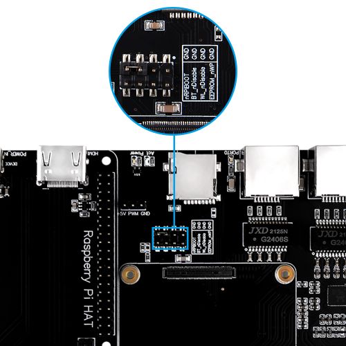
eMMC version CM4 burning switch
- nRPIBOOT - Bootloader
1. Connect a HDMI cable to see if the HDMI diagnostics screen appears.
2. Short the nRPIBOOT pin to ground to force USB boot mode. The CM4 Router board has a jumper for nRPIBOOT This can be used to enable different boot modes (e.g. network) and enable UART logging.
a. See [[ https://www.raspberrypi.org/documentation/hardware/computemodule/cm-emmc-flashing.md ]]
- WL_nDisable
This pin serves a number of functions:
1. It can be used to monitor the enable/disable state of wireless networking.
A logic high means the wireless networking module is powered up.
2. When driven or tied low it prevents the wireles network module from powering up.
This is useful to reduce power consumption or in applications where it is required to physically ensure the wireless networking is disabled.
If theinterface is enabled after being disabled, the wireless interface driver needs reinitalised.
On CM4 modules without wireless, this pin is reserved.
- BT_nDisable
This pin serves a number of functions:
1. It can be used to monitor the enable/disable state of Bluetooth. A logic high means the Bluetooth module is powered up.
2. When driven, or tied low, it prevents the Bluetooth module from powering up.
This is useful to reduce power consumption, or in applications where it is required to physically ensure the Bluetooth is disabled.
If the interface is enabled after being disabled, the Bluetooth interface driver needs reinitalised.
On CM4 modules without wireless, this pin is reserved.
- EEPROM_nWP
It is recommended that final products pull this pin low to prevent the end users changing the contents of the on board EEPROM.
See the Raspberry Pi 4, Model B documentation for instructions on the software settings required to support EEPROM Write protection. [[ https://www.raspberrypi.org/documentation/hardware/raspberrypi/booteeprom.md#:~:text=EEPROM%20write%20protect ]]
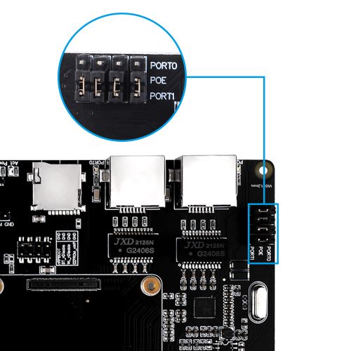
PoE Port Adjust Pin
It have 4 jumper caps, caps position configures POE to connect to Port 0 or Port 1
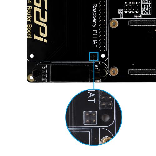
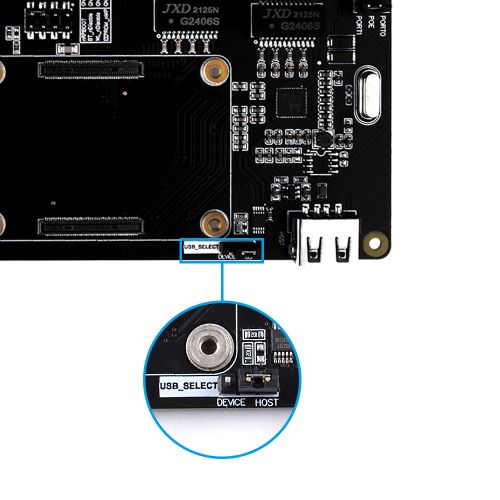
USB mode selection Pin
It is USB mode selection Pin, enabled by jumper caps, can change USB mode to Device mode and Host mode. Default mode is: USB 2.0 Host
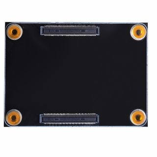
CM4 Attach Position
Note: Please pay attention to the direction of the slot, wrong direction or wrong angle may damage your CM4 Module.
0.91 inch OLED display
It communicate with Raspberry Pi CM4 via I2C protocol, it is based on SSD1306 chipset, 128x32 pixels resolution. It has been pre-installed on the CM4 router board and connect to CM4 on GPIO Pin number as following chart, and need to add `dtoverlay=i2c-gpio,i2c_gpio_sda=2,i2c_gpio_scl=3,i2c_gpio_delay_us=2,bus=1` to OpenWRT image's /boot/config.txt file which provides by 52Pi.
| OLED 0.91 | CM4 Router Board |
|---|---|
| VCC | 3.3V |
| GND | GND |
| SDA | GPIO2 (BCM Naming System) |
| SCL | GPIO3 (BCM Naming System) |
Package Includes
- 1 x CM4 Router Board
- 1 x Heatsink (Pre-installed)
- 1 x 0.91 Inch OLED Display (Pre-installed)
CM4 Datasheet
- CM4 Datasheet: [[ https://datasheets.raspberrypi.org/cm4/cm4-datasheet.pdf ]]
How to use
Requirements
- 1 x Any model of Compute Module 4
- 1 x 5V@3A USB-C power supply
- 1 x USB-C cable
- 1 x MicroSD card (If you use the eMMC model, you don't need a microSD card, but you need to prepare a USB-C cable for editing and burning eMMC)
- 2 x Cat-6 Ethernet Cable
How to connect network device
- Release the screws of pre-installed heatsink.
- Paste thermal pad to CM4 Module on top of CPU and Memory chip.
- Install Compute Module 4 to CM4 Router Board insert the microSD or TF card (eMMC version does not require an SD card)
- Fix the heatsink to CM4 router board.
- Connect the network cable to your network device and power on the router board.
- Port 0 - to LAN network device such as switch.
- Port 1 - to WAN network device as outgoing port.(also you can define it in routerOS such as OpenWRT)
Operating System
The CM4 router board is compatible with most systems that support Raspberry Pi 4, but most Linux distributions do not optimize the network device scenarios. So OpenWRT and Raspberry Pi OS are recommended.
For Raspberry Pi OS
- If you are using Raspberry Pi OS.
1. Enable USB2.0 Port: After flash the latest image file to TF card and then modify /boot/config.txt file and add following line to the file.
dtoverlay=dwc2,dr_mode=host
Save it and reboot Raspberry Pi. 2. Enable OLED onboard: 2.1 Enable I2C function, Open a terminal and typing:
sudo raspi-config
Navigate to `Interface Options` -> `I2C` -> `Enable` -> `YES`. 2.2 Download libaraies from github:
- Open a terminal and Download demo code from: [ https://github.com/adafruit/Adafruit_Python_SSD1306 ]
sudo python -m pip install --upgrade pip setuptools wheel
git clone https://github.com/adafruit/Adafruit_Python_SSD1306.git
cd Adafruit_Python_SSD1306
sudo python setup.py install
pip install Adafruit-BBIO
- Run example Demo:
cd examples/
python stats.py
For Using OpenWRT
Download Firmware
- 52Pi Version: Based on the latest development version of OpenWRT, which already includes the web interface and language pack, it is recommended to get started.
- 52Pi Official OpenWRT firmware [ https://github.com/geeekpi/cm4routerboard ]
OpenWRT Referrence Documentations
- OpenWRT official snapshot version
The official snapshot is the smallest system, using serial terminal control, you need to manually install the Web console, driver, etc. it is recommended for experienced users.
- OpenWRT official website: [ https://openwrt.org/ ]
- OpenWRT Develop Guide: [ https://openwrt.org/docs/guide-developer/source-code/start ]
- OpenWRT User Guide: [ https://openwrt.org/docs/guide-user/start ]
- OpenWRT forum: [ https://openwrt.org/contact#forum ]
- OpenWRT on Raspberry Pi CM4: [ https://openwrt.org/toh/hwdata/raspberry_pi_foundation/raspberry_pi_foundation_raspberry_pi_cm4 ]
- OpenWRT Raspberry Pi Foundation: [ https://openwrt.org/toh/raspberry_pi_foundation/raspberry_pi ]
- OpenWRT Use BuildSystem: [ https://openwrt.org/docs/guide-developer/build-system/use-buildsystem ]
- OpenWRT Build-System: [ https://openwrt.org/docs/guide-developer/build-system/install-buildsystem ]
SD Card Installation
Suitable for Compute Module 4 Lite without eMMC version.
- 1. Requirements
- Card Reader
- Etcher
- 7-Zip Compressed File Manager
- OS image file
Flash the image file to MicroSD card by using etcher imaging tool.
Build OpenWRT Customized Firmware
You can build your own firmware by building OpenWRT from source.
- 1.Prepare Compile Environment
- Flash the latest version of Raspberry Pi OS to TF card(32GB recommended).
- Modify /boot/config.txt file and adding the following parameter to enable the USB port function:
dtoverlay=dwc2,dr_mode=host
- Insert the TF card into card slot on CM4 Router Board.
- Connect the power supply(5V/3A) on USB-C port.
- After booting up the system, please connect to internet and typing following command in a terminal:
sudo apt-get update
sudo apt-get -y upgrade
- Install dependencies packages:
sudo apt-get -y install build-essential asciidoc binutils bzip2 libncurses5-dev flex git-core p7zip p7zip-full
sudo apt-get -y install libssl-dev libelf-dev autoconf automake libtool device-tree-compiler gettext libi2c-dev
sudo apt-get -y install libz-dev texinfo
- After installing, please reboot your Raspberry Pi CM4 by typing:
sudo sync && sudo reboot
- Create a folder and download OpenWRT source code by using git tool:
mkdir openwrt && cd openwrt
git clone --depth=1 https://github.com/openwrt/openwrt
cd openwrt/
./scripts/feeds update -a
./scripts/feeds install -a
- Download `luci-app-oled` libraries.
cd ~/openwrt/openwrt/package/feeds/luci/
git clone https://github.com/NateLol/luci-app-oled.git
cd ~/openwrt/openwrt/
./scripts/feeds update -a
./scripts/feeds install -a
- Download RTL8168 driver source code and put it into openwrt/package/ folder
URL: [ https://www.realtek.com/en/component/zoo/category/network-interface-controllers-10-100-1000m-gigabit-ethernet-pci-express-software ] Download it and unzip it to openwrt/package/ folder
- Configure the compile options by typing:
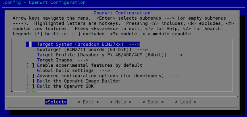
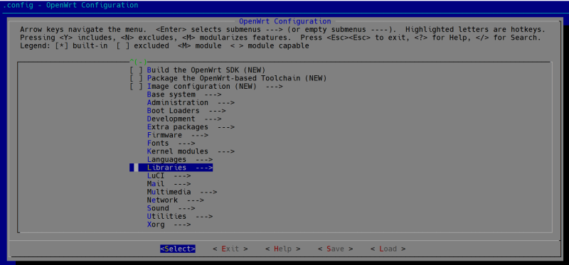
make menuconfig
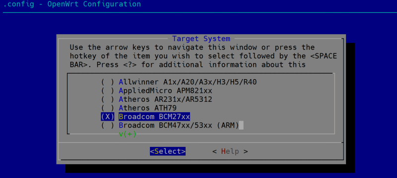
And then select "Target System" and "Target Profile" as following picture:
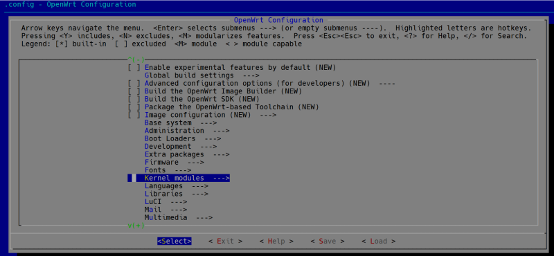
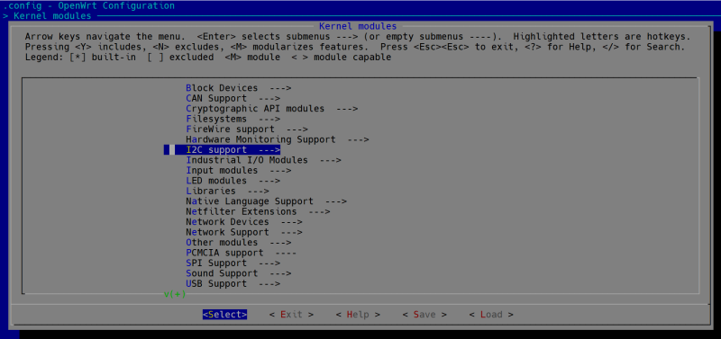
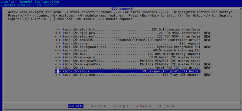
Navigate to `kernel modules` and select `kmod-i2c-xxx` as following picutres:
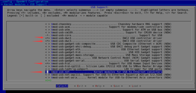
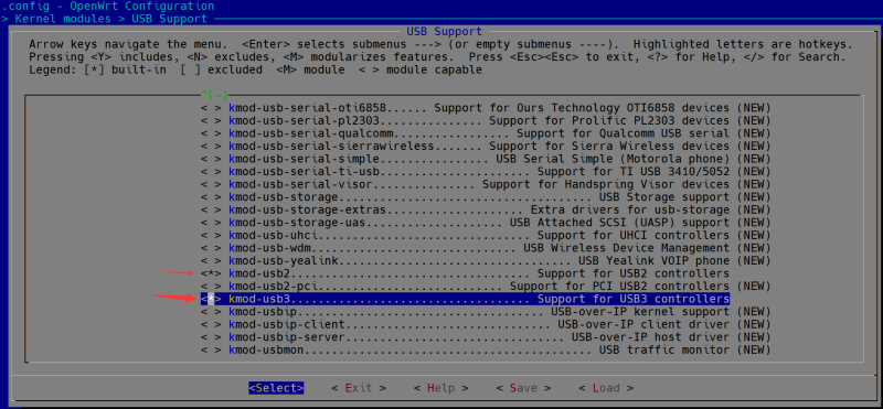
And then navigate to `USB Support` to add usb2 and usb3 support.
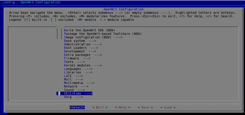
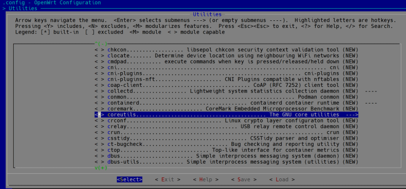
And then select `coreutils` in `Utilites` menu.
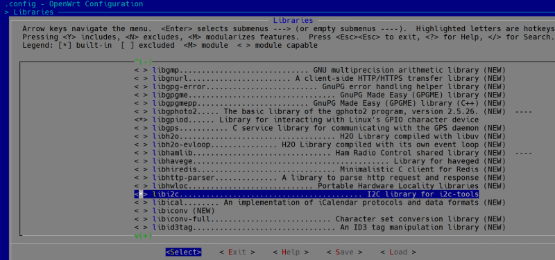
and enable `libi2c` in `libraries` menu.
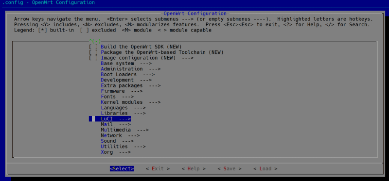
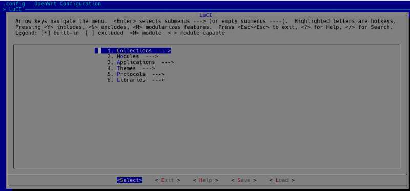
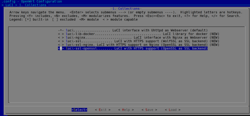
Next step is to enable LuCI `Collections` and `applications`.
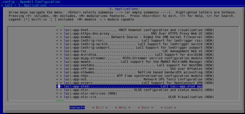
Navigate to `Applications` -> `luci-app-oled` and check it:
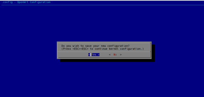
Save the configuration to `.config` file
- Compile it with following command:
make V=s -j1
It may take a while, grap a cup of coffee.
- Firmware will be generated on location:
~/openwrt/openwrt/bin/targets/bcm27xx/
- Factory image file: openwrt-bcm27xx-bcm2711-rpi-4-ext4-factory.img.gz or openwrt-bcm27xx-bcm2711-rpi-4-squashfs-factory.img.gz
- Sysupgrade image file: openwrt-bcm27xx-bcm2711-rpi-4-ext4-sysupgrade.img.gz or openwrt-bcm27xx-bcm2711-rpi-4-squashfs-sysupgrade.img.gz
- Flash the facotory image file to TF card via using `etcher` tool and insert the TF card to CM4_router_board, connect the 5V power supply.
- After booting, please connect your PC or just using Raspberry Pi to the ethernet cable on CM4 Router Board in `port0` or `port1`, and then open a browser, and typing administration address:
192.168.1.1
- Account: root
- Password is not set. please change the password once you login.
Enable I2C device in Customized OpenWRT
- Modify `/boot/config.txt` file and add this line:
dtoverlay=i2c-gpio,i2c_gpio_sda=2,i2c_gpio_scl=3,i2c_gpio_delay_us=2,bus=1
Save it and reboot Raspberry Pi CM4 Router Board.
- Change the Permission of `/etc/init.d/oled` file:
chmod 755 /etc/init.d/oled
/etc/init.d/oled restart
reboot
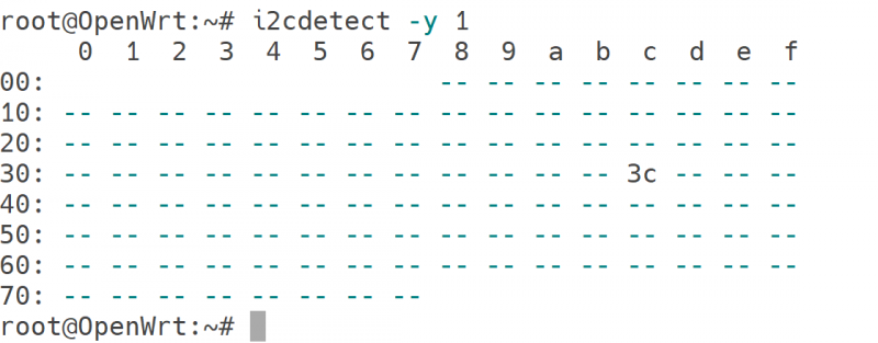
- After reboot, try to test if it can detect the oled's address `0x3C`
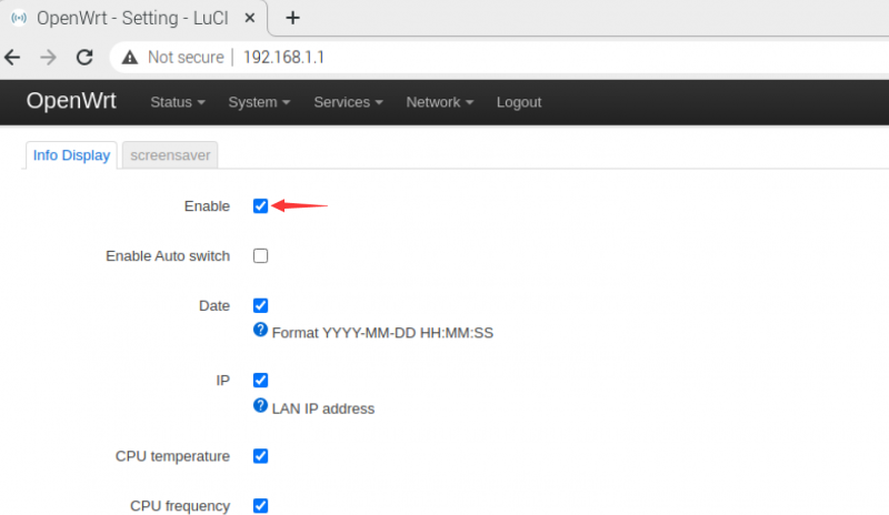
- Login to LuCI interface via browser and enable it, and then you can find the OLED in `service` tab, you can configure it as the notifications.
- Check the checkbox on `enable` and click `save it and apply`.
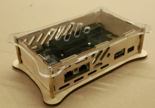
DIY Case
- Thanks to Dirk Feyerabend for his contribution to this project, it is a very cool case.
- OpenLaserCase for 52pi CM4 Router Board: [ https://www.thingiverse.com/thing:5449554 ]
