EP-0105
IoT Node(A)
- Purchase URL [ https://52pi.com/products/52pi-iot-nodea-for-raspberry-pi ]
Descriptions
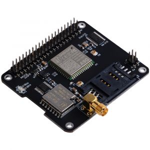
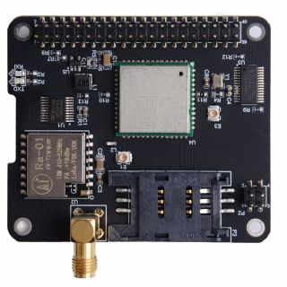
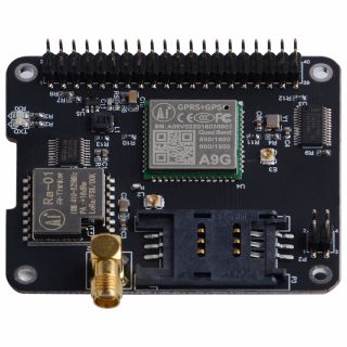
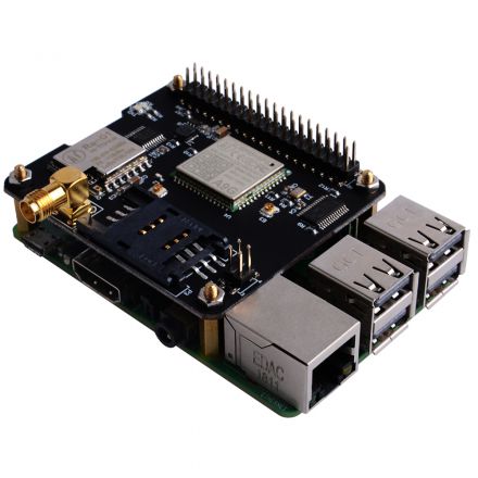
IoT Node(A) is one of Docker Pi series module.
IOT Node(A) = GPS/BDS + GSM + Lora.
I2C directly controls Lora, sends and receives data, controls the GSM/GPS/BDS module through SC16IS752, the mainboard only needs I2C support.
Support Raspberry Pi and other similar products.
Features
- DockerPi Series
- Programmable
- Control directly(without programming)
- Extend the GPIO Pins
- GPS/BDS Support
- GSM Support
- Lora Support
- Can Stack with other Stack board
- Independent of the mainboard hardware (require I2C support)
Official Compatibility Test
Not only support the following development boards, other development boards can be compatible if they have I2C peripherals. (Note: some software changes may be required)
| Platform | DockerPi IoT Node(A) | Notes |
|---|---|---|
| Raspberry Pi All Platform | √ | Not Include CM Series & EOL Platform |
Specifications
GPRS section
- 1. Low power consumption, standby sleep current <1mA
- 2. Support GSM/GPRS four frequency bands, including 850, 900, 1800, 1900MHZ;
- 3. GPRS Class 10;
- 4. Support GPRS data service, maximum data rate, download 85.6Kbps, upload 42.8Kbps;
- 5. Support standard GSM07.07, 07.05 AT commands, and access the serial port through I2C interface conversion.
- 6. AT commands support standard AT and TCP/IP command ports
GPS section
- 1. Support BDS/GPS joint positioning
- 2. Support A-GPS, A-BDS
- 3. Support standard SIM card
LORA section
- 1. Transmission distance:500 Meters (RF parameters: 0x50 @ China City)
- 2. Support FSK, GFSK, MSK, GMSK, LoRaTM and OOK modulation methods
- 3. Ultra-high receiver sensitivity as low as -141 dBm
- 4. Support preamble detection
- 5. Packet engine with CRC, up to 256 bytes
- 6. LORA transceiver indicator
- 7. Easy TX/RX by Docker Pi
- 8. Lora Freq: 433MHz
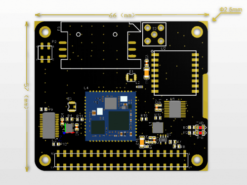
Mechanical Drawings
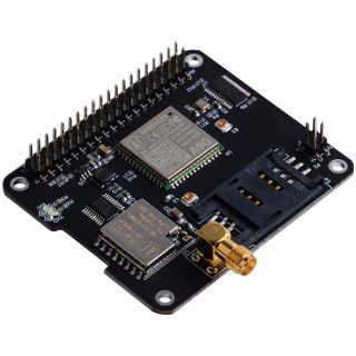
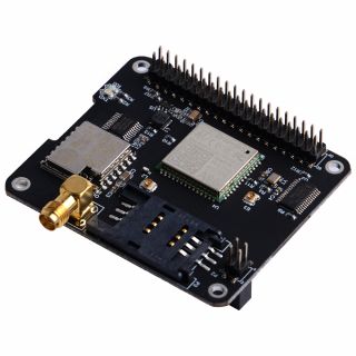
Gallery
Package Include
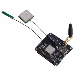
- 1 x IoT Node(A) Board
- 1 x Instructions
- 4 x M2.5*12 + 6 Copper stick
- 4 x M2.5*6 Nut
- 4 x M2.5*6 Half-round head screw
- 1 x 433MHz L-Shaped Tape Antenna
- 1 x 2.4GHz PCB Antenna
- 1 x GPS/BDS High Gain GPS Built-in Ceramic Active Antenna
On Board Modules Documentations
- A9G Module Spicification: File:A9g product specification.pdf
- A9G Module AT Command Manual: File:A9G AT COMMAND manual.pdf
- A9G GPRS Instruction Set v1.0 File:A9G gprs series module at instruction set v1.0.pdf
- GPRS C SDK: File:GPRS C SDK-master.zip
Technical Details
A9G Module
- A9G module offers two serial port.
- Use I2C <=> UART bridge for communication.
| Serial Port | Module name |
|---|---|
| /dev/ttySC0 | GSM |
| /dev/ttySC1 | GPS/BDS |
Register Map
| Register Address | Function | Value |
|---|---|---|
| 0x01 | LORA_TX1 | Lora TX Buffer 1 - User Data |
| 0x02 | LORA_TX2 | Lora TX Buffer 2 - User Data |
| 0x03 | LORA_TX3 | Lora TX Buffer 3 - User Data |
| 0x04 | LORA_TX4 | Lora TX Buffer 4 - User Data |
| 0x05 | LORA_TX5 | Lora TX Buffer 5 - User Data |
| 0x06 | LORA_TX6 | Lora TX Buffer 6 - User Data |
| 0x07 | LORA_TX7 | Lora TX Buffer 7 - User Data |
| 0x08 | LORA_TX8 | Lora TX Buffer 8 - User Data |
| 0x09 | LORA_TX9 | Lora TX Buffer 9 - User Data |
| 0x0a | LORA_TX10 | Lora TX Buffer 10 - User Data |
| 0x0b | LORA_TX11 | Lora TX Buffer 11 - User Data |
| 0x0c | LORA_TX12 | Lora TX Buffer 12 - User Data |
| 0x0d | LORA_TX13 | Lora TX Buffer 13 - User Data |
| 0x0e | LORA_TX14 | Lora TX Buffer 14 - User Data |
| 0x0f | LORA_TX15 | Lora TX Buffer 15 - User Data |
| 0x10 | LORA_TX16 | Lora TX Buffer 16 - User Data |
| 0x11 | LORA_RX1 | Lora RX Buffer 1 - User Data |
| 0x12 | LORA_RX2 | Lora RX Buffer 2 - User Data |
| 0x13 | LORA_RX3 | Lora RX Buffer 3 - User Data |
| 0x14 | LORA_RX4 | Lora RX Buffer 4 - User Data |
| 0x15 | LORA_RX5 | Lora RX Buffer 5 - User Data |
| 0x16 | LORA_RX6 | Lora RX Buffer 6 - User Data |
| 0x17 | LORA_RX7 | Lora RX Buffer 7 - User Data |
| 0x18 | LORA_RX8 | Lora RX Buffer 8 - User Data |
| 0x19 | LORA_RX9 | Lora RX Buffer 9 - User Data |
| 0x1a | LORA_RX10 | Lora RX Buffer 10 - User Data |
| 0x1b | LORA_RX11 | Lora RX Buffer 11 - User Data |
| 0x1c | LORA_RX12 | Lora RX Buffer 12 - User Data |
| 0x1d | LORA_RX13 | Lora RX Buffer 13 - User Data |
| 0x1e | LORA_RX14 | Lora RX Buffer 14 - User Data |
| 0x1f | LORA_RX15 | Lora RX Buffer 15 - User Data |
| 0x20 | LORA_RX16 | Lora RX Buffer 16 - User Data |
- 0x01 - 0x10 Write Only.
- 0x11 - 0x20 Read Only.
| Register Address | 0x22 | |||||||
|---|---|---|---|---|---|---|---|---|
| Name | - | SpreadingFactor | SignalBandwidth | ErrorCoding | ||||
| Default Value | 0 | 1 | 0 | 1 | 1 | 0 | 1 | 1 |
| Description | Reserved | Band range 7-12 | Spread spectrum bandwidth 6-9 | Effective data ratio 1-4 | ||||
- It is recommended to keep the default unless you know the meaning of the LORA parameter.
| Register Address | 0x23 | |||||||
|---|---|---|---|---|---|---|---|---|
| Default Value | 0 | 0 | 0 | 0 | 0 | 0 | 0 | 0 |
| Description | L_SET | G_RESET | Reserved | Reserved | Reserved | Reserved | L_RXNE | L_TX |
- L_SET(Write Only)
- Write 1 to set parameters from 0x22 to LORA Module.
- Write 0 not effect
- G_RESET(Write Only)
- Write 1 to reset A9G Module
- Write 0 not effect
- L_RXNE(Read & Write)
- Write 1 cause error
- Write 0 to clear
- Read 1 means data has been received, please get the data from the register 0x11 - 0x20.
- Read 0 means no data available now.
- L_SET(Write Only)
- Write 1 to send data,please fill in the data in register 0x01 - 0x10 before send.
- Write 0 not effect
How to use
How to assemble
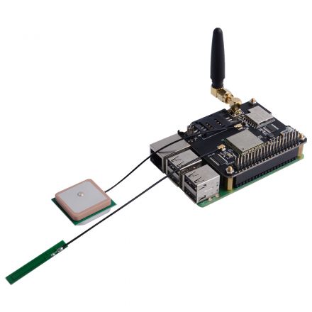
- Mount the Iot Node(A) board to Raspberry Pi
- Hookup GPS antana and Lora antana to IPEX port.
 E1:GPS-ANTANA-IPEX
 E3:GPRS-ANTANA-IPEX
- Screws the Lora Antana on the SMA port.
Configuring I2C(Raspberry Pi)
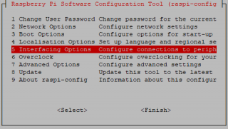
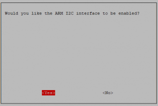
Run sudo raspi-config and follow the prompts to install i2c support for the ARM core and linux kernel
Go to Interfacing Options
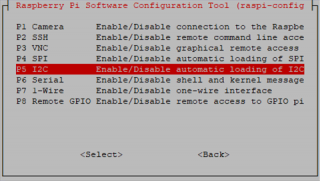
then I2C
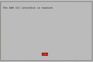
Enable!
Done!
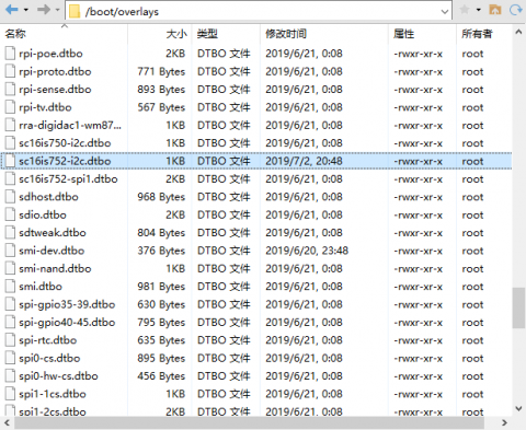
Replace /boot/overlays/sc16is752-i2c.dtbo(Raspberry Pi)
Replace /boot/overlays/sc16is752-i2c.dtbo file with this file: File:Sc16is752-i2c.zip
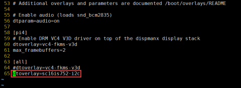
Modify /boot/config.txt file and add following parameter:
dtoverlay=sc16is752-i2c
And then save it and reboot Raspberry Pi.
- After rebooting, two serial devices will be detected in following location:
/dev/ttySC0
/dev/ttySC1
How to use GPS Module with gpsd(Raspberry Pi)
A) First, replace the /boot/overlays/sc16is752-i2c.dtbo and make sure I2C is working properly.
B)Install gpsd tools.
sudo apt install gpsd gpsd-clients
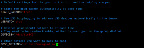
C)Modify /etc/default/gpsd file and add following parameters:
DEVICES="/dev/ttySC1"
GPSD_OPTIONS="-F /var/run/gpsd.sock"
D)Enter command i2cset -y 1 0x16 0x23 0x40 to reset the GPRS module.
E)Python Script For Open GPS:
- Install pyserial module before testing.
sudo pip3 install pyserial
- Write Demo code as following:
import serial
import os
import time

# Restart gpsd service.
os.system("sudo systemctl restart gpsd.socket")
# Open serial port
ser = serial.Serial('/dev/ttySC0', 115200)

i = 0

if ser.isOpen == False:
    ser.open()
try:
    print("Turn on GPS...")
    while True:
        ser.write(str.encode("AT+GPS=1\r"))
        size = ser.inWaiting()
        if size != 0:
            ticks = time.time()
            response = ser.read(size)
            gps = str(response,encoding="utf-8")
            if(gps.find("OK") != -1):
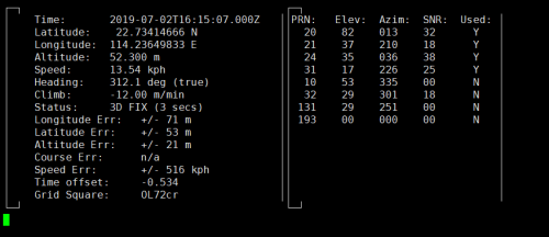
                os.system("sudo cgps -s")
                exit()
            else:
                i = i + 1
                print("Waiting GPS Enable, If the time is too long, Please test outdoors:" + str(i))
                ser.flushInput()
                time.sleep(1)
except KeyboardInterrupt:
    ser.flushInput()
    ser.close()
F)Save it and execute it:
python3 GPS.py
How to use GPS Module with C(Raspberry Pi)
A)Install gpsd tools.
sudo apt-get install libgps-dev
B)Create source code and name it "gps.c"
#include <gps.h>
#include <stdio.h>
#include <stdlib.h>
#include <unistd.h>
#include <math.h>

int main()
{
   int rc;
   struct timeval tv;
   struct gps_data_t gps_data;
   if ((rc = gps_open("localhost", "2947", &gps_data)) == -1)
   {
      printf("code: %d, reason: %s\n", rc, gps_errstr(rc));
      return EXIT_FAILURE;
   }

   gps_stream(&gps_data, WATCH_ENABLE | WATCH_JSON, NULL);

   while (1)
   {
      /* wait for 2 seconds to receive data */
      if (gps_waiting(&gps_data, 2000000))
      {
         /* read data */
         if ((rc = gps_read(&gps_data)) == -1)
         {
            printf("error occured reading gps data. code: %d, reason: %s\n", rc, gps_errstr(rc));
         }
         else
         {
            /* Display data from the GPS receiver. */
            if ((gps_data.status == STATUS_FIX) && (gps_data.fix.mode == MODE_2D || gps_data.fix.mode == MODE_3D) && !isnan(gps_data.fix.latitude) && !isnan(gps_data.fix.longitude))
            {
               /* gettimeofday(&tv, NULL); EDIT: tv.tv_sec isn't actually the timestamp! */

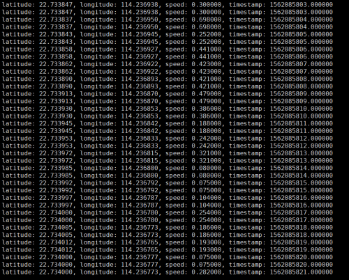
               printf("latitude: %f, longitude: %f, speed: %f, timestamp: %lf\n", gps_data.fix.latitude, gps_data.fix.longitude, gps_data.fix.speed, gps_data.fix.time);
               //EDIT: Replaced tv.tv_sec with gps_data.fix.time
            }
            else
            {
               printf("no GPS data available\n");
            }
         }
      }
      sleep(3);
   }
   /* When you are done... */
   gps_stream(&gps_data, WATCH_DISABLE, NULL);
   gps_close(&gps_data);
   return EXIT_SUCCESS;
}
Compile!
gcc gps.c -lm -lgps -o gps
Exec It!
./gps
How to use GPS Module with Python(Raspberry Pi)
The following code is recommended to be executed using Python 3 and install the gpsd-py3 library and GPS 2D/3D Fix:
import gpsd

# Connect to the local gpsd
gpsd.connect()

# Get gps position
packet = gpsd.get_current()

# See the inline docs for GpsResponse for the available data
print(packet.position())
How to use GSM Module with PPPd(Raspberry Pi)
A) First, replace the /boot/overlays/sc16is752-i2c.dtbo and make sure I2C is working properly.
B)Enter command i2cset -y 1 0x16 0x23 0x40 to reset the GPRS module.
- After running the command, you need to wait a little, about 10 seconds.
- You can also use the following method to reset.[[5]]
C)Enter command sudo apt install ppp to install ppp tools.
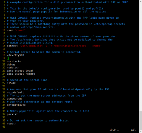
D)Copy /etc/ppp/peers/provider to /etc/ppp/peers/gprs
E)Modify /etc/ppp/peers/gprs
- Line 10 : Please consult your service provider for the user (Example:cmnet).
- Line 15 : Please consult your service provider for the apn (Example:cmnet).
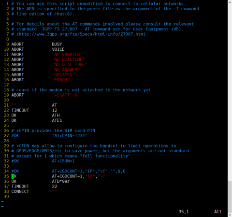
- Line 18 - Line 24:Recommended setting
F)Modify /etc/chatscripts/gprs (Change Line 34 to Line 35,Dialout Number May be NOT *99#)
G)Enter command sudo pppd call gprs to dial up.
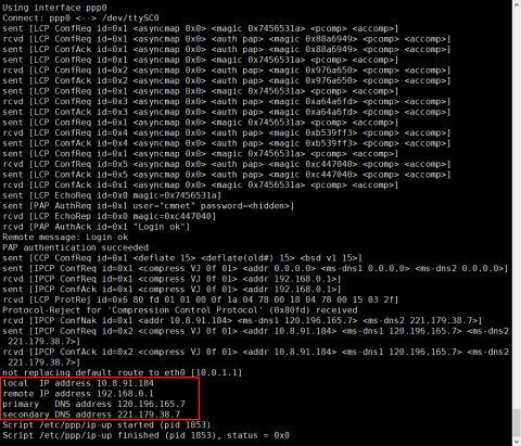
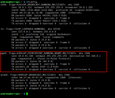
H)Check your ppp config from your ISP.
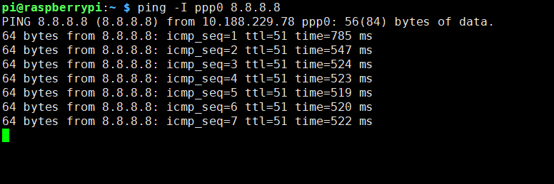
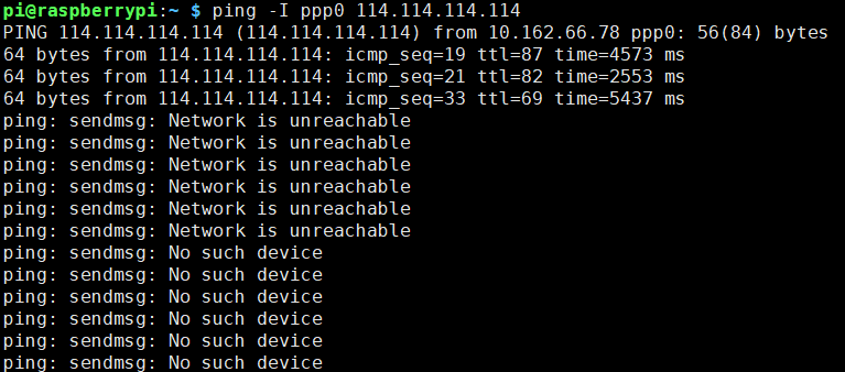
I)Enter command ping -I ppp0 8.8.8.8 test your network (If Internet available and route table is correct)
J)Please keep the GSM signal good, otherwise the following will occur.
How to diagnose my GSM Module(Raspberry Pi)
The following code is recommended to be executed using Python 3 and install the smbus library:
import serial
import time
import smbus
import operator
import os

print("Waiting for initializing...")

bus = smbus.SMBus(1)
bus.write_byte_data(0x16,0x23,0x40)

ser = serial.Serial('/dev/ttySC0', 115200)

if ser.isOpen == False:
    ser.open()
try:
    print('-'*60)
    print("Initializing A9G GPRS module.")
    print("GSM connecting...")
    time.sleep(3)
    i = 0
    while True:
        ser.write(str.encode("AT+CCID\r"))
        size = ser.inWaiting()
        if size != 0:
            ticks = time.time()
            response = ser.read(size)
            ccid = str(response,encoding="utf-8")
            print(ccid)
        else:
            i = i + 1
            ser.flushInput()
            time.sleep(1)
except KeyboardInterrupt:
    ser.close()
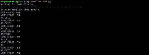
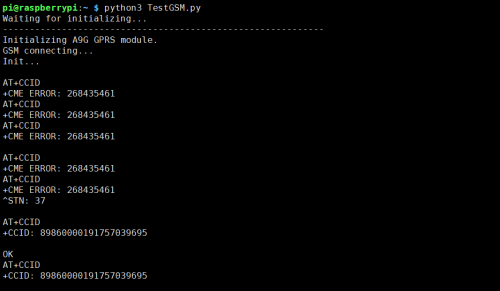
Exec the Test Script,based on the results of the implementation, we can diagnose the GSM module.
For example, the following return, CME ERROR 53 error tell us Power not good.
CME Code = GSM Equipment Related errors
Of course, the script also has a reset function. If you can display the CCID correctly, the reset is complete.
Press Ctrl-C to kill this script.
Dialout log reference(Raspberry Pi)
For quick troubleshooting, please refer to other documents for more details.
Script /usr/sbin/chat -s -v -f /etc/chatscripts/gprs -T cmnet finished (pid 1025), status = 0x0
Serial connection established.
using channel 1
Using interface ppp0
Connect: ppp0 <--> /dev/ttyUSB0
sent [LCP ConfReq id=0x1 <asyncmap 0x0> <magic 0x93623f70> <pcomp> <accomp>]
rcvd [LCP ConfReq id=0x1 <asyncmap 0x0> <auth pap> <magic 0xb90fa> <pcomp> <accomp>]
sent [LCP ConfAck id=0x1 <asyncmap 0x0> <auth pap> <magic 0xb90fa> <pcomp> <accomp>]
rcvd [LCP ConfAck id=0x1 <asyncmap 0x0> <magic 0x93623f70> <pcomp> <accomp>]
sent [LCP EchoReq id=0x0 magic=0x93623f70]
sent [PAP AuthReq id=0x1 user="cmnet" password=<hidden>]
rcvd [LCP EchoRep id=0x0 magic=0xb90fa]
rcvd [PAP AuthAck id=0x1 "Login ok"]
Remote message: Login ok
PAP authentication succeeded
sent [CCP ConfReq id=0x1 <deflate 15> <deflate(old#) 15> <bsd v1 15>]
sent [IPCP ConfReq id=0x1 <compress VJ 0f 01> <addr 0.0.0.0> <ms-dns1 0.0.0.0> <ms-dns2 0.0.0.0>]
rcvd [IPCP ConfReq id=0x1 <compress VJ 0f 01> <addr 192.168.0.1>]
sent [IPCP ConfAck id=0x1 <compress VJ 0f 01> <addr 192.168.0.1>]
rcvd [LCP ProtRej id=0x2 80 fd 01 01 00 0f 1a 04 78 00 18 04 78 00 15 03 2f]
Protocol-Reject for 'Compression Control Protocol' (0x80fd) received
rcvd [IPCP ConfNak id=0x1 <addr 10.188.229.78> <ms-dns1 211.136.17.107> <ms-dns2 211.136.20.203>]
sent [IPCP ConfReq id=0x2 <compress VJ 0f 01> <addr 10.188.229.78> <ms-dns1 211.136.17.107> <ms-dns2 211.136.20.203>]
rcvd [IPCP ConfAck id=0x2 <compress VJ 0f 01> <addr 10.188.229.78> <ms-dns1 211.136.17.107> <ms-dns2 211.136.20.203>]
not replacing default route to eth0 [10.0.1.1]
local  IP address 10.188.229.78
remote IP address 192.168.0.1
primary   DNS address 211.136.17.107
secondary DNS address 211.136.20.203
Script /etc/ppp/ip-up started (pid 1034)
Script /etc/ppp/ip-up finished (pid 1034), status = 0x0
How to use Lora TX & RX with C(Raspberry Pi)
It must be transferred between the two IOT Node(A). The content sent by itself cannot be received by itself.
- How to Send:After filling the data into register 0x01 - 0x10, set the L_TX bit to start sending data.
#include <stdio.h>
#include <wiringPi.h>
#include <wiringPiI2C.h>

int main(){
  int fd;

  fd = wiringPiI2CSetup(0x16);

  wiringPiI2CWriteReg8(fd,1,0xAA);
  wiringPiI2CWriteReg8(fd,2,0x55);
  wiringPiI2CWriteReg8(fd,3,0xA5);
  wiringPiI2CWriteReg8(fd,4,0x5A);

  wiringPiI2CWriteReg8(fd,0x23,0x01);
}
- How to Send Receive:Check L_RXNE bit,If set,new data arrived,this flag must be manually clear.
#include <stdio.h>
#include <wiringPi.h>
#include <wiringPiI2C.h>

int main(){
  int fd;
  int ret[4];

  fd = wiringPiI2CSetup(0x16);

  if (wiringPiI2CReadReg8(fd, 0x23) & 0x02 )
  {
    ret[0] = wiringPiI2CReadReg8(fd, 0x11);
    ret[1] = wiringPiI2CReadReg8(fd, 0x12);
    ret[2] = wiringPiI2CReadReg8(fd, 0x13);
    ret[3] = wiringPiI2CReadReg8(fd, 0x14);

    printf("Received data:0x%02X,0x%02X,0x%02X,0x%02X",ret[0],ret[1],ret[2],ret[3])
  }else{
    printf("No data Received yet~")
  }
}
How to use Lora TX & RX with Python(Raspberry Pi)
The following code is recommended to be executed using Python 3 and install the smbus library.
It must be transferred between the two IOT Node(A). The content sent by itself cannot be received by itself. Please save it as a py script for execution.
- How to Send:After filling the data into register 0x01 - 0x10, set the L_TX bit to start sending data.
import time
import smbus
import os
import sys

bus = smbus.SMBus(1)

try:
    data_list = [170,85,165,90]

    # write data to register and then the data will be send out.
    for index in range(1,len(data_list) + 1):
        bus.write_byte_data(0x16,index,data_list[index - 1])
        print("LORA send data to %d register %d data" %(index, data_list[index - 1]))

    bus.write_byte_data(0x16,0x23,0x01)
except KeyboardInterrupt:
    sys.exit()
- How to Send Receive:Check L_RXNE bit,If set,new data arrived,this flag must be manually clear.
import time
import smbus
import os
import sys

bus = smbus.SMBus(1)
recv_data = []

try:
    if bus.read_byte_data(0x16,0x23) & 0x02 :
        # manually clear L_RXNE
        bus.write_byte_data(0x16,0x23,0x00)
        register_list = [0x11,0x12,0x13,0x14]

        # read out data
        for index in range(0x11,len(register_list) + 0x11):
            recv_data.append(bus.read_byte_data(0x16, register_list[index - 0x11]))

        print("Received data:")
        print(recv_data)
    else :
        print("No data Received yet~")
except KeyboardInterrupt:
    sys.exit()
Special description of I2C bandwidth
- The limit of the I2C speed is 400kHz,due to the I2C protocol,so the single device effective bandwidth is lower than 320kbps,multi device effective bandwidth is lower than 160kbps.
- The limit of the I2C <=> UART Bridge speed is 115200bps.
- When GPS and GSM work at the same time, I2C bandwidth is insufficient,because 115.2kbps * 2 = 230.4kbps,so some data will be overflow.
- Reducing the baud rate of GPS and GSM communication can improve the communication bandwidth shortage.
- Stacking other DockerPi modules may take up extra I2C bandwidth.
- At usually, the network data speed is slow, so the GSM bandwidth is not full, so there is no overflow problem.
FAQ
- Q: What mean of +CME ERROR: 58 ? do you have ERROR code ?
A: Please check following chart.
CME ERROR (GSM Equipment Related errors)
Error	Description
CME ERROR: 0	Phone failure
CME ERROR: 1	No connection to phone
CME ERROR: 2	Phone adapter link reserved
CME ERROR: 3	Operation not allowed
CME ERROR: 4	Operation not supported
CME ERROR: 5	PH_SIM PIN required
CME ERROR: 6	PH_FSIM PIN required
CME ERROR: 7	PH_FSIM PUK required
CME ERROR: 10	SIM not inserted
CME ERROR: 11	SIM PIN required
CME ERROR: 12	SIM PUK required
CME ERROR: 13	SIM failure
CME ERROR: 14	SIM busy
CME ERROR: 15	SIM wrong
CME ERROR: 16	Incorrect password
CME ERROR: 17	SIM PIN2 required
CME ERROR: 18	SIM PUK2 required
CME ERROR: 20	Memory full
CME ERROR: 21	Invalid index
CME ERROR: 22	Not found
CME ERROR: 23	Memory failure
CME ERROR: 24	Text string too long
CME ERROR: 25	Invalid characters in text string
CME ERROR: 26	Dial string too long
CME ERROR: 27	Invalid characters in dial string
CME ERROR: 30	No network service
CME ERROR: 31	Network timeout
CME ERROR: 32	Network not allowed, emergency calls only
CME ERROR: 40	Network personalization PIN required
CME ERROR: 41	Network personalization PUK required
CME ERROR: 42	Network subset personalization PIN required
CME ERROR: 43	Network subset personalization PUK required
CME ERROR: 44	Service provider personalization PIN required
CME ERROR: 45	Service provider personalization PUK required
CME ERROR: 46	Corporate personalization PIN required
CME ERROR: 47	Corporate personalization PUK required
CME ERROR: 48	PH-SIM PUK required
CME ERROR: 100	Unknown error
CME ERROR: 103	Illegal MS
CME ERROR: 106	Illegal ME
CME ERROR: 107	GPRS services not allowed
CME ERROR: 111	PLMN not allowed
CME ERROR: 112	Location area not allowed
CME ERROR: 113	Roaming not allowed in this location area
CME ERROR: 126	Operation temporary not allowed
CME ERROR: 132	Service operation not supported
CME ERROR: 133	Requested service option not subscribed
CME ERROR: 134	Service option temporary out of order
CME ERROR: 148	Unspecified GPRS error
CME ERROR: 149	PDP authentication failure
CME ERROR: 150	Invalid mobile class
CME ERROR: 256	Operation temporarily not allowed
CME ERROR: 257	Call barred
CME ERROR: 258	Phone is busy
CME ERROR: 259	User abort
CME ERROR: 260	Invalid dial string
CME ERROR: 261	SS not executed
CME ERROR: 262	SIM Blocked
CME ERROR: 263	Invalid block
CME ERROR: 527	Please wait, and retry your selection later (Specific Modem Sierra)
CME ERROR: 528	Location update failure – emergency calls only (Specific Modem Sierra)
CME ERROR: 529	Selection failure – emergency calls only (Specific Modem Sierra)
CME ERROR: 772	SIM powered down
- Q: GPS Status always NO FIX?
A: GPS must be used outdoors,It may take up to 15 minutes for the first use.
- Q: Unable to open serial port?
A: Check permissions, dialout groups, and whether other software is occupying the serial port.
- Q: PPP No internet access,How can I do?
A: Consult your ISP service provider.
- Q: Dose CDMA Support?
A: No.
- Q: I can't use the BDS system.
A: Available only in China and parts of Asia.
- Q: The network speed is too slow.
A: 2G network is unable to compare speed with 5G network.
- Q: Can I use other GPS antennas?
A: Yes, but please be careful not to use antennas that exceed the GPS power limit.
- Q: My SIM card has no signal, but it works fine on the mobile phone. Why?
A: Make sure your location 2G network is well covered & Make sure your carrier does not ban your 2G network.
- Q: PPP have internet access,but can't ping any website?
A: Try to run route add -net 0.0.0.0 ppp0
- Q: GSM Connect script failed,How to do?
A: Try to run i2cset -y 1 0x16 0x23 0x40 and wait 1 minutes.If Failed,Please check your SIM card.
- Q: Why I get "timeout sending Config-Requests"?
A: Please check the antenna and 2G signal conditions..
- Q: Could not determine local IP address,How can I do?
A: The program will try again until it fails. If it fails, please try again later, or contact the ISP to resolve it.
- Q: Could not determine remote IP address,How can I do?
A: Your ISP limits how your SIM is used.
- Q: What is China Dialout Number?
A: WCDMA(*99#) CDMA(#777) TD-SCDMA(981#) GPRS/EGDE(99**1#)
- Q: What is Other Region Dialout Number?
A: Ask your ISP provider.
- Q: pppd call gprs can dial successfully but ping -I ppp0 8.8.8.8 fail,How can I do?
A: If there is no problem with the previous script, if you run pppd call gprs succes, and ifpconfig can view the ppp0 network card. However, if you have enabled Ethernet eth0 before dialing, you can use the ppp0 NIC to ping the specified ip or domain name ping -I ppp0 8.8.8.8 and it will not succeed for two reasons. One is the default gateway in the routing table. It was generated by eth0 before, and one is the default dns server address.After the defaultroute is enabled in the pppd script, pppd will add a default gateway information to the routing table after dialing successfully. However, because there is already a default gateway, the addition fails. The default gateway is still set by the previous eth. Before pppd call gprs we should first route del default to delete the default route (preferably write a script to delete the default route - dialing and other operations).
- Q: Dial stability is relatively poor, Why?
A: Because 2G coverage is getting lower and lower, you can use a more powerful antenna or add the lcp-echo-interval parameter.
- Q: Why I get UnicodeDecodeError: 'utf8' codec can't decode byte 0xXX ?
A: Please refer => IoT_Node(A)_SKU:_EP-0105#Replace_.2Fboot.2Foverlays.2Fsc16is752-i2c.dtbo.28Raspberry_Pi.29
Keywords
- IoT,Lora,GPS,GPRS,GSM,Node,radio devices,BDS
