EP-0099
DockerPi 4 Channel Relay
Description
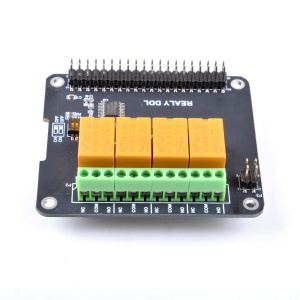
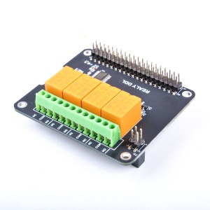
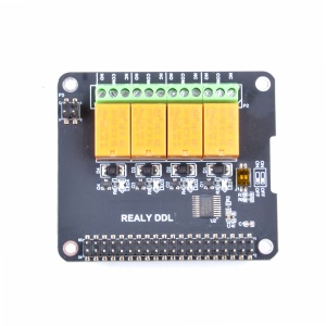
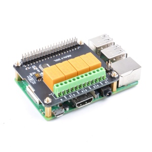
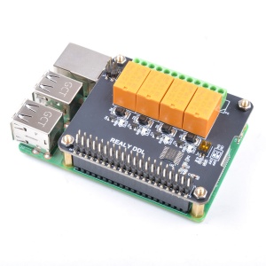
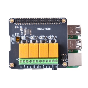
DockerPi 4 Channel Relay is a member of the DockerPi Series,more commonly used in IOT applications.
DockerPi 4 Channel Relay can relay AC/DC, instead of traditional switches, to achieve more ideas.
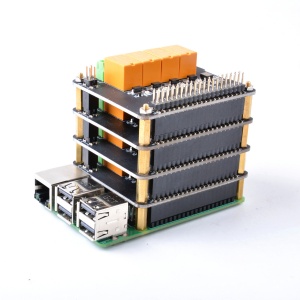
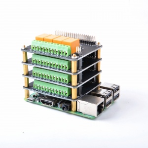
DockerPi 4 Channel Relay can stack up to 4, and can be stacked with other DockerPi expansion board. If you need to run for a long time, we also recommend that you use our DockerPi Power expansion board to provide more power.
Features
- MCU Power IN: 5V (via GPIO pin)
- DockerPi Series
- Programmable
- Control directly(without programming)
- Extend the GPIO Pins
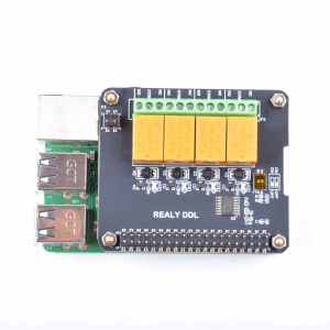
- 4 Channel Relay
- 4 Alt I2C Addr Support
- Relay Status Leds
- Support 3A 250V AC
- Support 3A 30V DC
- Can Stack with other Stack board
- Independent of the mainboard hardware (require I2C support)
- Compatible with 24AWG-30AWG wire
Official Compatibility Test
Not only support the following development boards, other development boards can be compatible if they have I2C peripherals. (Note: some software changes may be required)
| Platform | DockerPi 4 Channel Relay | Notes |
|---|---|---|
| Raspberry Pi All Platform | √ | Not Include CM Series & EOL Platform |
| Banana Pi M3 | √ | Python 3 & Modify DEVICE_BUS to 2 |
| ASUS Tinker Board | √ | Python 3 & Modify DEVICE_BUS to 1 |
| Orange Pi Zero | √ | Python 3 & Modify DEVICE_BUS to 0 |
Gallery
Package Include
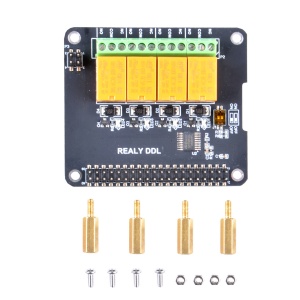
- 1 x Docker Pi 4 Channel Relay
- 1 x Instruction
- 4 x M2.5*11 + 6 Copper stick
- 4 x M2.5*6 Nut
- 4 x M2.5*6 Half-round head screw
Device Address Map
| DIP switch status icon | Device Address |
|---|---|
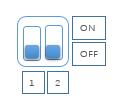 |
0x10 |
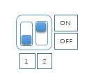 |
0x11 |
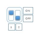 |
0x12 |
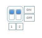 |
0x13 |
Register Map
| Register Address | Function | Value |
|---|---|---|
| 0x01 | Relay 1 | 0(FULL OFF) - 1/255(ON) |
| 0x02 | Relay 2 | 0(FULL OFF) - 1/255(ON) |
| 0x03 | Relay 3 | 0(FULL OFF) - 1/255(ON) |
| 0x04 | Relay 4 | 0(FULL OFF) - 1/255(ON) |
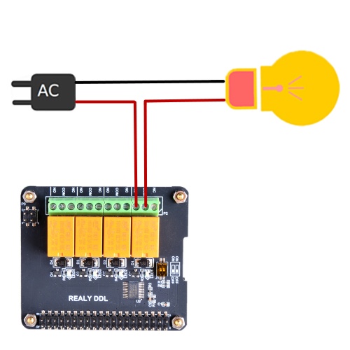
How to connect electrical device
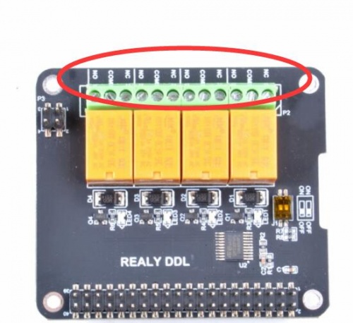
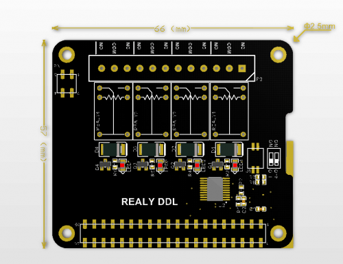
Please pay attention to this mark on the board:
- NC = Normal Close
- COM = Common
- NO = Normal Open
Mechanical Drawing
Configuring I2C(Raspberry Pi)
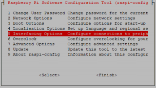
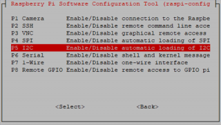
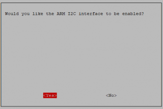
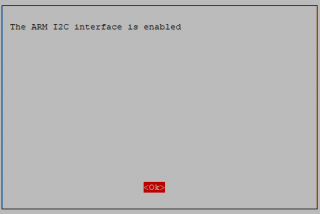
Run sudo raspi-config and follow the prompts to install i2c support for the ARM core and linux kernel
Go to Interfacing Options
then I2C
Enable!
Done!
Direct control without programming(Raspberry Pi)
- Turn on channel No.1 relay
i2cset -y 1 0x10 0x01 0xFF
- Turn off channel No.1 relay
i2cset -y 1 0x10 0x01 0x00
- Turn on channel No.2 relay
i2cset -y 1 0x10 0x02 0xFF
- Turn off channel No.2 relay
i2cset -y 1 0x10 0x02 0x00
- Turn on channel No.3 relay
i2cset -y 1 0x10 0x03 0xFF
- Turn off channel No.3 relay
i2cset -y 1 0x10 0x03 0x00
- Turn on channel No.4 relay
i2cset -y 1 0x10 0x04 0xFF
- Turn off channel No.4 relay
i2cset -y 1 0x10 0x04 0x00
Program in Language C(Raspberry Pi)
Create source code and name it "relay.c"
#include <stdio.h>
#include <wiringPi.h>
#include <wiringPiI2C.h>

#define DEVCIE_ADDR  0x10
#define RELAY1  0x01
#define RELAY2  0x02
#define RELAY3  0x03
#define RELAY4  0x04
#define ON      0xFF
#define OFF     0x00

int main(void){
    printf("Turn on Relays in C\n");
    int fd;
    int i = 0;
    fd = wiringPiI2CSetup(DEVICE_ADDR);
    for(;;){
       for (i=1; i<=4; i++){
          printf("turn on relay No.%d\n", i);
          wiringPiI2CWriteReg8(fd, i, ON);
          sleep(200);
          printf("turn off relay No.%d\n", i);
          wiringPiI2CWriteReg8(fd, i, OFF);
          sleep(200);
       }
    }
    return 0;
}
Compile!
gcc relay.c -lwiringPi -o relay
Exec It!
./relay
Program in Python(Raspberry Pi)
The following code is recommended to be executed using Python 3 and install the smbus library:
import time as t
import smbus
import sys

DEVICE_BUS = 1
DEVICE_ADDR = 0x10
bus = smbus.SMBus(DEVICE_BUS)

while True:
    try:
        for i in range(1,5):
            bus.write_byte_data(DEVICE_ADDR, i, 0xFF)
            t.sleep(1)
            bus.write_byte_data(DEVICE_ADDR, i, 0x00)
            t.sleep(1)
    except KeyboardInterrupt as e:
        print("Quit the Loop")
        sys.exit()
Program in Java(Raspberry Pi)
Create a new file named: I2CRelay.java and paste following code:
import java.io.IOException;
import java.util.Arrays;

import com.pi4j.io.i2c.I2CBus;
import com.pi4j.io.i2c.I2CDevice;
import com.pi4j.io.i2c.I2CFactory;
import com.pi4j.io.i2c.I2CFactory.UnsupportedBusNumberException;
import com.pi4j.platform.PlatformAlreadyAssignedException;
import com.pi4j.util.Console;

public class I2CRelay {

    // relay's register address.
    public static final int DOCKER_PI_RELAY_ADDR = 0x10;

    // channel of relay.
    public static final byte DOCKER_PI_RELAY_1 = (byte)0x01;
    public static final byte DOCKER_PI_RELAY_2 = (byte)0x02;
    public static final byte DOCKER_PI_RELAY_3 = (byte)0x03;
    public static final byte DOCKER_PI_RELAY_4 = (byte)0x04;

    // Relay status
    public static final byte DOCKER_PI_RELAY_ON = (byte)0xFF;
    public static final byte DOCKER_PI_RELAY_OFF = (byte)0x00;

    public static void main(String[] args) throws InterruptedException, PlatformAlreadyAssignedException, IOException, UnsupportedBusNumberException {

        final Console console = new Console();

        I2CBus i2c = I2CFactory.getInstance(I2CBus.BUS_1);
        I2CDevice device = i2c.getDevice(DOCKER_PI_RELAY_ADDR);

        console.println("Turn on Relay!");
        device.write(DOCKER_PI_RELAY_1, DOCKER_PI_RELAY_ON);

        Thread.sleep(500);

        console.println("Turn off Relay!");
        device.write(DOCKER_PI_RELAY_1, DOCKER_PI_RELAY_OFF);
    }
}
- Compile it and running:
javac I2CRelay.java -classpath .:classes:/opt/pi4j/lib/'*'
sudo java -classpath .:classes:/opt/pi4j/lib/'*' I2CRelay
Customer Application
- Thanks for 11je [ https://plus.google.com/114848996385924765358 ] provides a demo that using 4 Channel Relay works with Arduino IDE.
- Project URL: [ https://www.instructables.com/I2C-Relay-Met-Arduino-IDE/ ]
Git Repository
You can also clone the repository from github:
sudo apt-get update
sudo apt-get -y install git
git clone https://github.com/geeekpi/dockerpi
cd dockerpi/
Running Differenet program with different way.
