EP-0098
DockerPi NightLight
Description
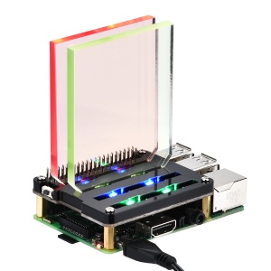
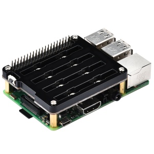
DockerPi NightLight is a DockerPi series expansion board with 8 WS2812 RGB LEDs. The expansion board communicates with I2C protocol. It can be used in Raspberry Pi, Jetson Nano and other single board computers (require I2C peripherals).
You can programmatically control the color of each LED, such as Python or C, or you can control the color of each LED directly through system commands without programming. Most Linux distributions include the i2c-tools, which allows you to control this.
DockerPi NightLight can only be used one, but can be stacked with other DockerPi expansion board. If you need to run for a long time, we also recommend that you use our DockerPi Power expansion board to provide more power.
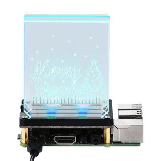
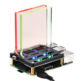
The module is stacked on the top layer and can be placed with acrylic decoration for better show.
Features
- DockerPi Series
- Programmable
- Control directly(without programming)
- Extend the GPIO Pins
- WS2812 RGB LEDs
- Independent control of each LED
- 2 * Demo acrylic supports your quick start
- 2 * Blank acrylic supports your custom ideas
- Recommended to be stacked at the top
- Can Stack with other Stack board
- Independent of the mainboard hardware (require I2C support)
Official Compatibility Test
Not only support the following development boards, other development boards can be compatible if they have I2C peripherals. (Note: some software changes may be required)
| Platform | DockerPi Nightlight | Notes |
|---|---|---|
| Raspberry Pi All Platform | √ | Not Include CM Series & EOL Platform |
| Banana Pi M3 | √ | Python 3 & Modify DEVICE_BUS to 2 |
| Orange Pi Zero | √ | Python 3 & Modify DEVICE_BUS to 0 |
Gallery
Package Includes
- 1 x DockerPi NightLight
- 4 x M2.5*12 + 6 Copper stick
- 4 x M2.5*6 Nut
- 4 x M2.5*6 Half-round head screw
- 1 x Instructions
- 1 x Acrylic Pattern Design (Stander)
- 4 x Acrylic Pattern Design (2x Demo and 2x Blank)
Register Map
| Register Address | Function | Value |
|---|---|---|
| 0x01 | LED1 Red | 0(FULL OFF) - 255(FULL ON) |
| 0x02 | LED1 Green | 0(FULL OFF) - 255(FULL ON) |
| 0x03 | LED1 Blue | 0(FULL OFF) - 255(FULL ON) |
| 0x04 | LED2 Red | 0(FULL OFF) - 255(FULL ON) |
| 0x05 | LED2 Green | 0(FULL OFF) - 255(FULL ON) |
| 0x06 | LED2 Blue | 0(FULL OFF) - 255(FULL ON) |
| 0x07 | LED3 Red | 0(FULL OFF) - 255(FULL ON) |
| 0x08 | LED3 Green | 0(FULL OFF) - 255(FULL ON) |
| 0x09 | LED3 Blue | 0(FULL OFF) - 255(FULL ON) |
| 0x0a | LED4 Red | 0(FULL OFF) - 255(FULL ON) |
| 0x0b | LED4 Green | 0(FULL OFF) - 255(FULL ON) |
| 0x0c | LED4 Blue | 0(FULL OFF) - 255(FULL ON) |
| 0x0d | LED5 Red | 0(FULL OFF) - 255(FULL ON) |
| 0x0e | LED5 Green | 0(FULL OFF) - 255(FULL ON) |
| 0x0f | LED5 Blue | 0(FULL OFF) - 255(FULL ON) |
| 0x10 | LED6 Red | 0(FULL OFF) - 255(FULL ON) |
| 0x11 | LED6 Green | 0(FULL OFF) - 255(FULL ON) |
| 0x12 | LED6 Blue | 0(FULL OFF) - 255(FULL ON) |
| 0x13 | LED7 Red | 0(FULL OFF) - 255(FULL ON) |
| 0x14 | LED7 Green | 0(FULL OFF) - 255(FULL ON) |
| 0x15 | LED7 Blue | 0(FULL OFF) - 255(FULL ON) |
| 0x16 | LED8 Red | 0(FULL OFF) - 255(FULL ON) |
| 0x17 | LED8 Green | 0(FULL OFF) - 255(FULL ON) |
| 0x18 | LED8 Blue | 0(FULL OFF) - 255(FULL ON) |
| 0x19 | Button | 0x01 - Button Pressed 0x00 - Button Released/Manually Reset |
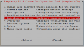
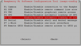
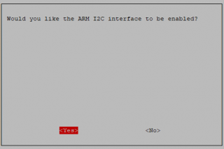
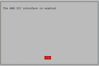
Configuring I2C(Raspberry Pi)
Run sudo raspi-config and follow the prompts to install i2c support for the ARM core and linux kernel
Go to Interfacing Options
then I2C
Enable!
Done!
Direct control without programming(Raspberry Pi)
The following script demonstrates turn on and turn off each LED.
#!/bin/bash

for i in $(seq 1 24)
do
        i2cset -y 1 0x15 $i 0xFF   # turn on the led
        sleep 0.5
        i2cset -y 1 0x15 $i 0x00   # turn of the led
        sleep 0.5
done
Program in Language C(Raspberry Pi)
Create source code and name it "led.c"
#include <stdio.h>
#include <wiringPi.h>
#include <wiringPiI2C.h>

#define BUTTON_REG_ADDR 0x19

int main(){
        int fd;
        int is_press = 1;
        int is_draw = 0;
        int i = 0;

        fd = wiringPiI2CSetup(0x15);

        for(i = 1;i<25;i++) wiringPiI2CWriteReg8(fd,i,0x00);

        for(;;)
        {
                if (wiringPiI2CReadReg8(fd, BUTTON_REG_ADDR) == 0x01 )
                {
                        is_press++;
                        is_draw = 1;
                        wiringPiI2CWriteReg8(fd,BUTTON_REG_ADDR, 0x0);
                }
                if(is_press && is_draw){
                        is_draw = 0;
                        for(i = 1;i<25;i++){
                                if(is_press > 3) is_press = 1;
                                if(((i + is_press) % 3) == 0)
                                {
                                        wiringPiI2CWriteReg8(fd,i,0xff);
                                }else{
                                        wiringPiI2CWriteReg8(fd,i,0x00);
                                }
                                delay(100);
                        }

                        wiringPiI2CWriteReg8(fd,BUTTON_REG_ADDR, 0x0);
                }
        }
}
Compile!
gcc led.c -lwiringPi -o led
Exec It!
./led
Program in Language Python(Raspberry Pi)
The following code is recommended to be executed using Python 3 and install the smbus library:
import time as t
import smbus
import sys

DEVICE_BUS = 1
DEVICE_ADDR = 0x15
bus = smbus.SMBus(DEVICE_BUS)

while True:
    try:
        for i in range(1,25):
            bus.write_byte_data(DEVICE_ADDR, i, 0xFF)
            t.sleep(0.2)
            bus.write_byte_data(DEVICE_ADDR, i, 0x00)
            t.sleep(0.2)
    except KeyboardInterrupt as e:
        sys.exit()
        print("Quit the Loop")
Program in Java(Raspberry Pi)
Create a new file named:NightLight.java and paste following code:
import java.io.IOException;
import java.util.Arrays;

import com.pi4j.io.i2c.I2CBus;
import com.pi4j.io.i2c.I2CDevice;
import com.pi4j.io.i2c.I2CFactory;
import com.pi4j.io.i2c.I2CFactory.UnsupportedBusNumberException;
import com.pi4j.platform.PlatformAlreadyAssignedException;
import com.pi4j.util.Console;

public class NightLight {

    public static final int DOCKERPI_NIGHTLIGHT_BOARD = 0x19;
    public static final byte RESET_BIT = (byte) 0x00;

    // NightLight Address
    public static final int NIGHTLIGHT_REG_ADDR = 0x15;

    // LED of NightLight
    public static final byte LED1_RED = (byte) 0x01;

    // NightLight LED status
    public static final byte NIGHTLIGHT_ON = (byte) 0xFF;
    public static final byte NIGHTLIGHT_OFF = (byte) 0x00;

    public static void main(String[] args)
            throws InterruptedException, PlatformAlreadyAssignedException, IOException, UnsupportedBusNumberException {

        int i = 1;
        final Console console = new Console();

        I2CBus i2c = I2CFactory.getInstance(I2CBus.BUS_1);
        I2CDevice device = i2c.getDevice(DOCKERPI_NIGHTLIGHT_BOARD);

        while (true) {
            if (device.read(BUTTON_ADDR) == 0x01) {
                console.println("the button has been pressed");
                device.write(BUTTON_ADDR, RESET_BIT);
                i++;
                if (i > 2) {
                    i = 1;
                }
            }
            if (i == 1) {
                console.println("Turn off LED!");
                device.write(LED1_RED, NIGHTLIGHT_OFF);
                Thread.sleep(5000);
            }
            if (i == 2) {
                console.println("Turn on LED!");
                device.write(LED1_RED, NIGHTLIGHT_ON);
                Thread.sleep(5000);
            }
        }
    }
}
- Compile it and running:
javac NightLight.java -classpath .:/opt/pi4j/lib/'*'
sudo java -classpath .:classes:/opt/pi4j/lib/'*' NightLight
Keywords
- DockerPi,RGB,RGB LED,WS2812,Colorful
Video Tutorial
- Please follow the link:
- [ DockerPi NightLight Board Tutorial| https://youtu.be/KI7cQQLffG0 ]
