EP-0116
DockerPi-H Board
Open Source Description
Anyone may use the content of the white paper for non-commercial or educational purposes without permission without the permission of the source and copyright notice, but it may not be used for profit or commercial purposes without permission.
Custom product LOGO is NOT allowed without copyright notice,Open source does not mean arbitrary use of trademarks!
Welcome to submit links to your project(or tips),after our review, we will link your project in GitHub Page.
Android and IOS app source code provided by NordicSemiconductor.
Product Description
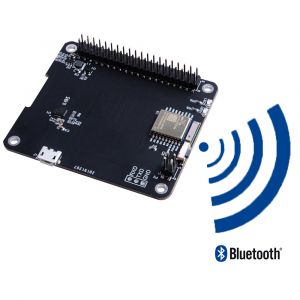
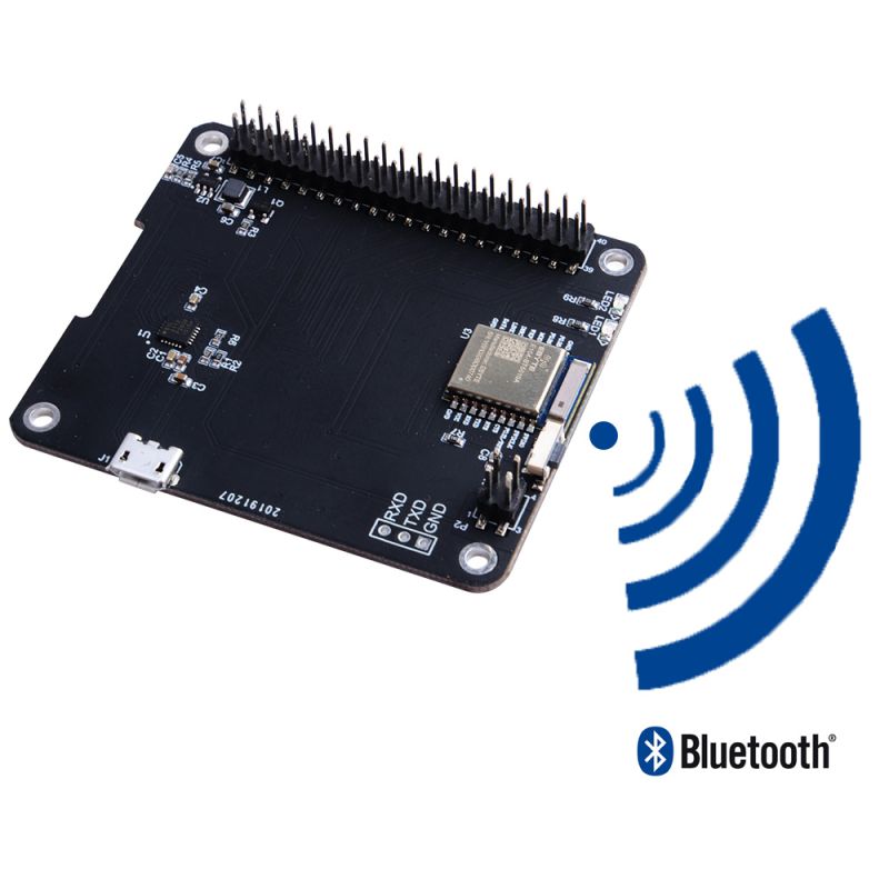
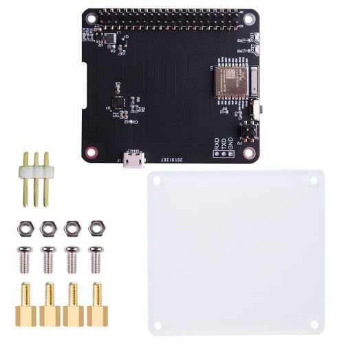
DockerPi-H is one of the DockerPi series expansion boards, which can convert I2C communication of other products in the DockerPi series to UART (TTL) / HID / BLE.
BLE is usually used for the Internet of Things, TTL is usually used for industrial control, HID can communicate without driver.
This product design for low power consumption, and can be maintained by only a few mA.
DockerPi-H allows you to operate DockerPi series expansion boards without Raspberry Pi (or similar SBC).
It can connect your personal computer to DockerPi expansion boards and also allows you to wirelessly control DockerPi expansion boards.
Features
- Open source project (not for commercial distribution)
- DockerPi series products
- Programmable, can work with mobile phones, personal computers, industrial computers, ITX.
- Support BLE, HID, UART-TTL to transmit data
- Support BLE, UART-TTL data in ASCII mode
- Support UART-TTL, HID data in HEX mode
- HID does not require driver support
- It is recommended to install at the bottom of all modules
- Low power design
- BLE module provides FCC / CE certification
Supported platforms
- 1. Tested Mobile devices : IPhone 6s Plus, HUAWEI SCM-AL09
- 2. Tested Platform : sscom.exe(Windows Environment), minicom(Linux Environment), pyserial module(via USB-to-TTL cable)
- 3. Supoort Interface : Bluetooth LE Only / USB HID / TTL UART
Sources Repository
- DockerPi-H Open Sources Page
- CP2112 Software package for Windows
- CP2112 Softare package for Linux
- CP2112 Software package for MAC
- NordicSemiconductor Open Sources Page
Gallery
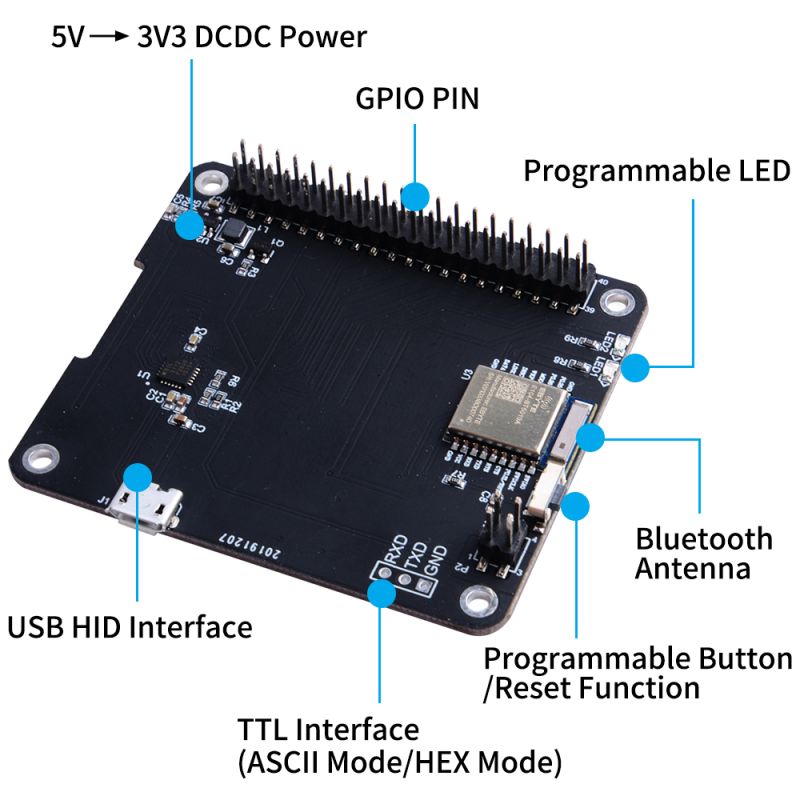
- Product Function:
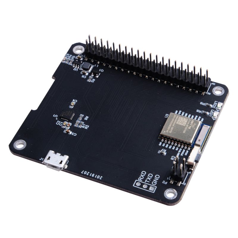
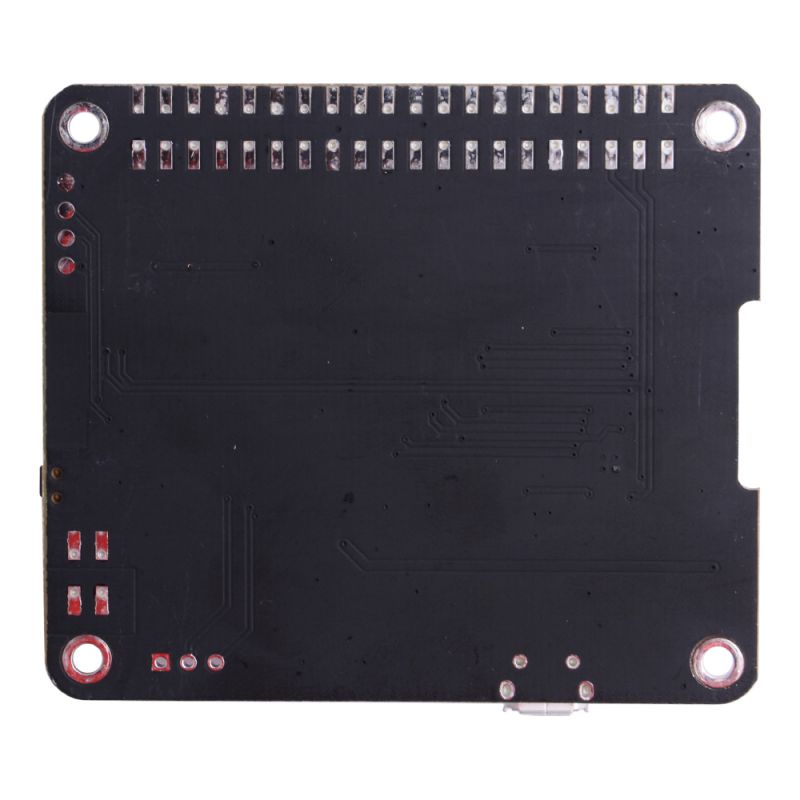
- Product View:
- Application View:
How to Use
HID Interface
The HID interface is implemented using CP2112, please refer to for more information. [ CP2112 Classic USB to HID Bridge ]
API Reference
File:An496-hid-usb-to-smbus-api-specification.pdf
Quick Reference
HidSmbus_WriteRequest
This function writes the specified number of bytes from the supplied buffer to the specified slave device and returns immediately after sending the request to the CP2112.
HidSmbus_AddressReadRequest
This function intiates a read transfer to the specified slave device address and specifies the address to read from on the device.
HidSmbus_ForceReadResponse
This function causes the device to send a read response to the host after a read transfer has been issued.
HidSmbus_GetReadResponse
This function returns the read response to a read request. Read and write timeouts as well as transfer retries can be set using HidSmbus_SetSmbusConfig() as described in HidSmbus_SetSmbusConfig.
Test Conditions
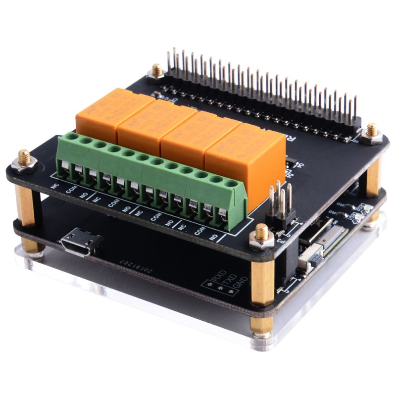
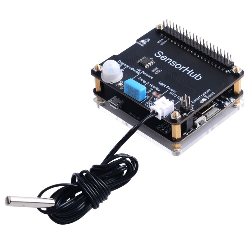
DockerPi SensorHub and DockerPi Relay need to be installed on the top of DockerPi-H.
Example Code(C#)
using System;
using System.Collections.Generic;
using System.ComponentModel;
using System.Data;
using System.Drawing;
using System.Linq;
using System.Text;
using System.Threading;
using System.Threading.Tasks;
using System.Windows.Forms;
using SLAB_HID_TO_SMBUS;

namespace WindowsFormsApp1
{
    public partial class Form1 : Form
    {
        const ushort vid = 4292;  //10C4
        const ushort pid = 60048; //EA90
        IntPtr connectedDevice;

        const byte RelaySlaveAddress = 0x20;
        const byte SensorSlaveAddress = 0x2E;

        ushort RelayStauts = 0;


        public Form1()
        {
            InitializeComponent();
            uint numDevices = 0;
            SLAB_HID_TO_SMBUS.CP2112_DLL.HidSmbus_GetNumDevices(ref numDevices, vid, pid);
            SLAB_HID_TO_SMBUS.CP2112_DLL.HidSmbus_Open(ref connectedDevice, 0, vid, pid);

            SLAB_HID_TO_SMBUS.CP2112_DLL.HidSmbus_WriteRequest(connectedDevice, RelaySlaveAddress, new byte[] { 0x01, 0x00 }, 2);

            timer_get_temp.Enabled = true;
        }

        private void RelayButton_Click(object sender, EventArgs e)
        {
            timer_get_temp.Enabled = false;

            if (RelayStauts == 0)
            {
                RelayStauts = 1;
                SLAB_HID_TO_SMBUS.CP2112_DLL.HidSmbus_WriteRequest(connectedDevice, RelaySlaveAddress, new byte[] { 0x01, 0xFF }, 2);

            }
            else
            {
                RelayStauts = 0;
                SLAB_HID_TO_SMBUS.CP2112_DLL.HidSmbus_WriteRequest(connectedDevice, RelaySlaveAddress, new byte[] { 0x01, 0x00 }, 2);
            }

            timer_get_temp.Enabled = true;
        }

        private void Timer_get_temp_Tick(object sender, EventArgs e)
        {

            byte bytesRead = 0;
            byte status = 0;
            byte[] readbuff = new byte[61];

            SLAB_HID_TO_SMBUS.CP2112_DLL.HidSmbus_AddressReadRequest(connectedDevice, SensorSlaveAddress, 1, 1, new byte[] { 0x01 });
            SLAB_HID_TO_SMBUS.CP2112_DLL.HidSmbus_ForceReadResponse(connectedDevice, 1);
            SLAB_HID_TO_SMBUS.CP2112_DLL.HidSmbus_GetReadResponse(connectedDevice, ref status, readbuff, 61, ref bytesRead);

             if(bytesRead == 1)
            {
                progressBar.Value = readbuff[0];
            }
        }
    }
}
UART Interface
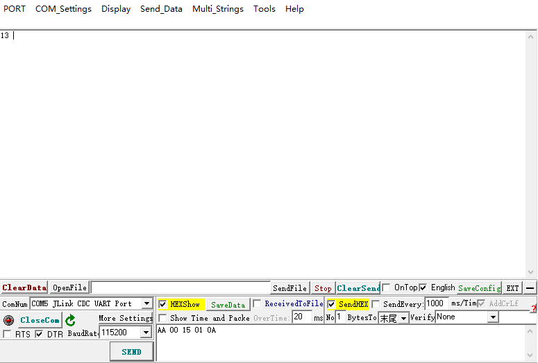
Serial interface supports ASCII mode or HEX mode transmission,3V3 TTL as voltage reference.
You can solder headers or use a jumper wire to connect to your device.
Mode:115200 8N1
Interface Protocol
Read Function:
| Function | Preamble | Direction | CHIP-ADDRESS | DATA-ADDRESS | END |
|---|---|---|---|---|---|
| Length | 1 | 1 | 1 | 1 | 1 |
| Comment | AA | 00 => i2c-get | I2C_ADDR_RANGE | DATA-ADDRESS | 0A/0D |
Write Function:
| Function | Preamble | Direction | CHIP-ADDRESS | DATA-ADDRESS | DATA | END |
|---|---|---|---|---|---|---|
| Length | 1 | 1 | 1 | 1 | * | 1 |
| Comment | AA | 01 => i2c-set | I2C_ADDR_RANGE | DATA-ADDRESS | DATA | 0A/0D |
How to Communicate
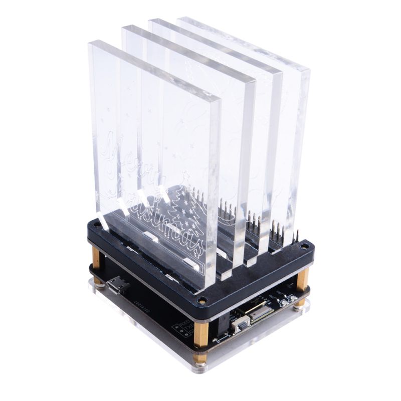
NightLight board's control bus is 1, I2C address is 0x15, and first LED register is 0x01, Turn on it by sending 0xFF The execution code is: AA011501FF The meaning of the code is: AA - starting code, DIR parameter 01 means write, 15 means I2C address 0x15, 01 means first LED register, FF eq 0xFF means Turn it on.
HEX Mode:
After sending each instruction, you need to send the 0A or 0D end this transaction.
ASCII Mode:
In ASCII mode, you must check AddCrLf.
NightLight board's control bus is 1, I2C address is 0x15, and first LED register is 0x01, Read back The execution code is: AA001501 The meaning of the code is: AA - starting code, DIR parameter 00 means read, 15 means I2C address 0x15, 01 means first LED register.
If you use HEX mode, you can return the result in HEX mode,If you use ASCII mode, you can return the result in ASCII mode,write operation returns nothing.
Bluetooth Interface
Bluetooth interface only provides LE only protocol support
LED Status
LED1:Link(ON) / Broadcast(Blink) / Fault(OFF)
LED2:Busy(ON)/ Transmission(Blink) / Idle(OFF)
Interface Protocol
Read Function:
| Function | Preamble | Direction | CHIP-ADDRESS | DATA-ADDRESS |
|---|---|---|---|---|
| Length | 1 | 1 | 1 | 1 |
| Comment | AA | 00 => i2c-get | I2C_ADDR_RANGE | DATA-ADDRESS |
Write Function:
| Function | Preamble | Direction | CHIP-ADDRESS | DATA-ADDRESS | DATA |
|---|---|---|---|---|---|
| Length | 1 | 1 | 1 | 1 | * |
| Comment | AA | 01 => i2c-set | I2C_ADDR_RANGE | DATA-ADDRESS | DATA |
Download SDK
- For IOS user
- nRF Toolbox Download Link: [ https://apps.apple.com/cn/app/nrf-toolbox/id820906058 ]
- For Android user
- nRF Toolbox Download Link: [ https://play.google.com/store/apps/details?id=no.nordicsemi.android.nrftoolbox ]
- For Sources code user
Development Method
- 1. Download SDK from the links mentioned before and install it to IOS device or Android device.
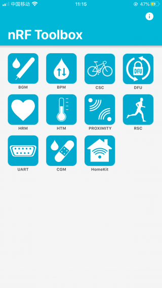
- 2. Open the nRF Toolbox app
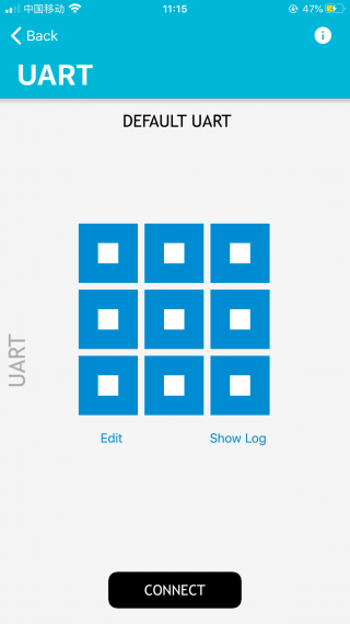
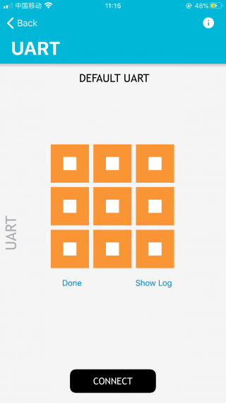
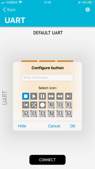
- 3. Select "UART" icon and press "Edit"
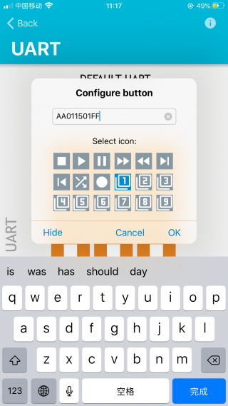
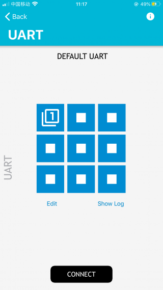
- 4. Select one icon and input the execution code and press OK, and then press the icon will send the code to DockerPi Nightlight board.
- For example: Turn on NightLight board's first LED.
NightLight board's control bus is 1, I2C address is 0x15, and first LED register is 0x01, Turn on it by sending 0xFF
The execution code is: AA011501FF
The meaning of the code is: AA - starting code, DIR parameter 01 means write, 15 means I2C address 0x15, 01 means first LED register, FF eq 0xFF means Turn it on.
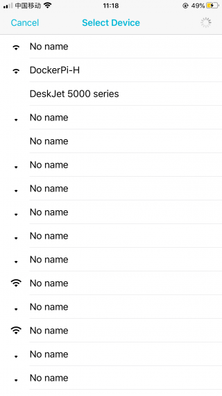
- 5. Press "Connect" to scan the DockerPi-H, and select it.
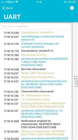
- 6.If the connection is successful, the blue LED will stop blinking and stay on.and you can see log by pressing "show log" link.
Product Includes
- 1 x DockerPi-H BlueTooth Board
- 1 x Acrylic Plate
- 1 x 3-Pin Pin Header
- 4 x M2.5 Nut
- 4 x M2.5 Screw
- 4 x M2.5x6 Copper Stick
FAQ
- Q: Should I connect DockerPi-H to my Raspberry Pi to make it work?
A: No, the DockerPi-H is seperated from Raspberry Pi, all you need to do is connect other DockerPi product such as Nightlight board or 4 channel relay board to it and control it via bluetooth.
- Q: Can I just using DockerPi-H to build my own project without other DockerPi product?
A: No, DockerPi-H is built for DockerPi series product so that you should have another DockerPi series product at least.
- Q: A write I2C operation has been performed but nothing return?
A: Only read operations can return.
- Q: Whether the UART interface can be directly connected to the RS232 connection terminal?
A: The voltages are not compatible and you need to level shift.
Keywords
- GeeekPi, dockerPi, dockerPi-H, bluetooth, BLE
