Z-0234
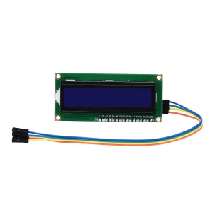
1602 Serial LCD Module Display

- Purchase URL [ https://52pi.com/products/52pi-i2c-1602-lcd-display-module-16x2-character-serial-blue-yellow-backlight-lcd-module ]
Description
As we know, the LCD1602 is an industrial character LCD that can display 16x02 or 32 characters at the same time.
The principle of the LCD1602 liquid crystal display is to use the physical characteristics of the liquid crystal to control the display area by voltage,
that is, the graphic can be displayed.
In general, the 1602 uses a standard 16-pin interface, and our display module is a module that provides I2C functionality.
I²C uses only two bidirectional open-drain lines, Serial Data Line (SDA) and Serial Clock Line (SCL),
pulled up with resistors. Typical voltages used are +5 V or +3.3 V although systems with other voltages are permitted.
It can be operated as long as it supports the I2C development board.
For example, the common Arduino, raspberry pi, Stm32 and so on.
Features
- Easy to use.
- Less I/O ports are occupied
- Support IIC Protocol.
- The I2C LCD1602 library is easy to get
- With a potentiometer used to adjust backlight and contrast
- Blue backlight
- Power supply: 5v
- I2C address is: new version is 0x3F, Old version is 0x27

NOTE: After continuous iteration, the new product has updated the address of the register. At present, the address of the latest product is 0x3F, and the original old version is 0x2F. For the difference method, please check that the silk screen of the adapter board on the back contains MH as the new version, and the distance between the sliding rheostat The bottom pad space is larger.

Package include
- 2 x Blue backlight I2C LCD1602(1602 Serial LCD Module Display
- 8 x Jump wire
How to connect it to Arduino
- Connect LCD1602 module to Arduino Uno board as following picture:
| I2C LCD1602 | Arduino Uno board |
|---|---|
| GND | GND |
| VCC | 5V |
| SDA | A4 /pin 20 mega2560 |
| SCL | A5 /pin 21 mega2560 |

How to connnect it to Raspberry Pi


How to test it
- Reference program writing:
(The following program can recognize the screen used for 27 address and 3F address at the same time)
Demo code in programming language C:
#include <Wire.h>
#include <LiquidCrystal_I2C.h>

void setup()
{
    byte error;
    Wire.begin();
    Wire.beginTransmission(0x27);
    error = Wire.endTransmission();
    if(error == 0){                      // If your device is 0x27
      LiquidCrystal_I2C lcd(0x27,20,4);
      lcd.init();
      lcd.backlight();
      lcd.setCursor(0,0);
      lcd.print("Device Addr = 0x27");
    }else{                               // If your device is 0x3F
      LiquidCrystal_I2C lcd(0x3F,20,4);
      lcd.init();
      lcd.backlight();
      lcd.setCursor(0,0);
      lcd.print("Device Addr = 0x3F");
    }
}

void loop(){}
- Compile it and run:
gcc test_led1602.c
./a.out
How to program it in Arduino
- 1.Download the LiquidCrystal_I2C library
- 2.Open the Arduino IDE,Select Sketch -> Include Library -> Add ZIP Library
- 3.Find the file LiquidCrystal_I2C which you just download.
- 4.Click it open and then you'll be prompted by "Library added to your libraries.
- 5.Check 'Import libraries'”.
- 6.Open file ->Sketch->Include Library->LiquidCrystal_I2C.
- 7.Copy the follwing code to the Arduino IDE ,click to the upload icon to upload the code to the control board:
#include <Wire.h>
#include <LiquidCrystal_I2C.h>

LiquidCrystal_I2C lcd(0x27, 16, 2); // set the LCD address to 0x27, if new version please use 0x3F instead.

void setup()
{
  lcd.init();  //initialize the lcd
  lcd.backlight();  //open the backlight
}

void loop()
{
  lcd.setCursor(3, 0); // set the cursor to column 3, line 0
  lcd.print("Hello GeeekPi");  // Print a message to the LCD

  lcd.setCursor(2, 1); // set the cursor to column 2, line 1
  lcd.print("hello world");  // Print a message to the LCD.
}
How to program it on Raspberry Pi
- ENABLE I2C ON THE PI
Before we get into the programming, we need to make sure the I2C module is enabled on the Pi and install a couple tools that will make it easier to use I2C.
- 1. ENABLE I2C IN RASPI-CONFIG
First, log in to your Pi and enter sudo raspi-config to access the configuration menu. Then arrow down and select “Advanced Settings”:

Now arrow down and select “I2C Enable/Disable automatic loading”:

Choose “Yes” at the next prompt, exit the configuration menu, and reboot the Pi to activate the settings.
- 2.INSTALL I2C-TOOLS AND SMBUS
Now we need to install a program called I2C-tools, which will tell us the I2C address of the LCD when it’s connected to the Pi.
So at the command prompt, enter
sudo apt-get install i2c-tools
Next we need to install SMBUS, which gives the Python library we’re going to use access to the I2C bus on the Pi.
At the command prompt, enter
sudo apt-get install python-smbus
Now reboot the Pi and log in again.
With your LCD connected, enter
i2cdetect -y 1
at the command prompt.
This will show you a table of addresses for each I2C device connected to your Pi:

The I2C address of my LCD is 27. Take note of this number, we’ll need it later.
Copy this code for the library, then save it in a file named I2C_LCD_driver.py:
# -*- coding: utf-8 -*-
# Original code found at:
# https://gist.github.com/DenisFromHR/cc863375a6e19dce359d

"""
Compiled, mashed and generally mutilated 2014-2015 by Denis Pleic
Made available under GNU GENERAL PUBLIC LICENSE

# Modified Python I2C library for Raspberry Pi
# as found on http://www.recantha.co.uk/blog/?p=4849
# Joined existing 'i2c_lib.py' and 'lcddriver.py' into a single library
# added bits and pieces from various sources
# By DenisFromHR (Denis Pleic)
# 2015-02-10, ver 0.1

"""

# i2c bus (0 -- original Pi, 1 -- Rev 2 Pi)
I2CBUS = 0

# LCD Address
ADDRESS = 0x27

import smbus
from time import sleep

class i2c_device:
   def __init__(self, addr, port=I2CBUS):
      self.addr = addr
      self.bus = smbus.SMBus(port)

# Write a single command
   def write_cmd(self, cmd):
      self.bus.write_byte(self.addr, cmd)
      sleep(0.0001)

# Write a command and argument
   def write_cmd_arg(self, cmd, data):
      self.bus.write_byte_data(self.addr, cmd, data)
      sleep(0.0001)

# Write a block of data
   def write_block_data(self, cmd, data):
      self.bus.write_block_data(self.addr, cmd, data)
      sleep(0.0001)

# Read a single byte
   def read(self):
      return self.bus.read_byte(self.addr)

# Read
   def read_data(self, cmd):
      return self.bus.read_byte_data(self.addr, cmd)

# Read a block of data
   def read_block_data(self, cmd):
      return self.bus.read_block_data(self.addr, cmd)


# commands
LCD_CLEARDISPLAY = 0x01
LCD_RETURNHOME = 0x02
LCD_ENTRYMODESET = 0x04
LCD_DISPLAYCONTROL = 0x08
LCD_CURSORSHIFT = 0x10
LCD_FUNCTIONSET = 0x20
LCD_SETCGRAMADDR = 0x40
LCD_SETDDRAMADDR = 0x80

# flags for display entry mode
LCD_ENTRYRIGHT = 0x00
LCD_ENTRYLEFT = 0x02
LCD_ENTRYSHIFTINCREMENT = 0x01
LCD_ENTRYSHIFTDECREMENT = 0x00

# flags for display on/off control
LCD_DISPLAYON = 0x04
LCD_DISPLAYOFF = 0x00
LCD_CURSORON = 0x02
LCD_CURSOROFF = 0x00
LCD_BLINKON = 0x01
LCD_BLINKOFF = 0x00

# flags for display/cursor shift
LCD_DISPLAYMOVE = 0x08
LCD_CURSORMOVE = 0x00
LCD_MOVERIGHT = 0x04
LCD_MOVELEFT = 0x00

# flags for function set
LCD_8BITMODE = 0x10
LCD_4BITMODE = 0x00
LCD_2LINE = 0x08
LCD_1LINE = 0x00
LCD_5x10DOTS = 0x04
LCD_5x8DOTS = 0x00

# flags for backlight control
LCD_BACKLIGHT = 0x08
LCD_NOBACKLIGHT = 0x00

En = 0b00000100 # Enable bit
Rw = 0b00000010 # Read/Write bit
Rs = 0b00000001 # Register select bit

class lcd:
   #initializes objects and lcd
   def __init__(self):
      self.lcd_device = i2c_device(ADDRESS)

      self.lcd_write(0x03)
      self.lcd_write(0x03)
      self.lcd_write(0x03)
      self.lcd_write(0x02)

      self.lcd_write(LCD_FUNCTIONSET | LCD_2LINE | LCD_5x8DOTS | LCD_4BITMODE)
      self.lcd_write(LCD_DISPLAYCONTROL | LCD_DISPLAYON)
      self.lcd_write(LCD_CLEARDISPLAY)
      self.lcd_write(LCD_ENTRYMODESET | LCD_ENTRYLEFT)
      sleep(0.2)


   # clocks EN to latch command
   def lcd_strobe(self, data):
      self.lcd_device.write_cmd(data | En | LCD_BACKLIGHT)
      sleep(.0005)
      self.lcd_device.write_cmd(((data & ~En) | LCD_BACKLIGHT))
      sleep(.0001)

   def lcd_write_four_bits(self, data):
      self.lcd_device.write_cmd(data | LCD_BACKLIGHT)
      self.lcd_strobe(data)

   # write a command to lcd
   def lcd_write(self, cmd, mode=0):
      self.lcd_write_four_bits(mode | (cmd & 0xF0))
      self.lcd_write_four_bits(mode | ((cmd << 4) & 0xF0))

   # write a character to lcd (or character rom) 0x09: backlight | RS=DR<
   # works!
   def lcd_write_char(self, charvalue, mode=1):
      self.lcd_write_four_bits(mode | (charvalue & 0xF0))
      self.lcd_write_four_bits(mode | ((charvalue << 4) & 0xF0))

   # put string function with optional char positioning
   def lcd_display_string(self, string, line=1, pos=0):
    if line == 1:
      pos_new = pos
    elif line == 2:
      pos_new = 0x40 + pos
    elif line == 3:
      pos_new = 0x14 + pos
    elif line == 4:
      pos_new = 0x54 + pos

    self.lcd_write(0x80 + pos_new)

    for char in string:
      self.lcd_write(ord(char), Rs)

   # clear lcd and set to home
   def lcd_clear(self):
      self.lcd_write(LCD_CLEARDISPLAY)
      self.lcd_write(LCD_RETURNHOME)

   # define backlight on/off (lcd.backlight(1); off= lcd.backlight(0)
   def backlight(self, state): # for state, 1 = on, 0 = off
      if state == 1:
         self.lcd_device.write_cmd(LCD_BACKLIGHT)
      elif state == 0:
         self.lcd_device.write_cmd(LCD_NOBACKLIGHT)

   # add custom characters (0 - 7)
   def lcd_load_custom_chars(self, fontdata):
      self.lcd_write(0x40);
      for char in fontdata:
         for line in char:
            self.lcd_write_char(line)
please modify this paragraph according to your Pi version.
# i2c bus (0 -- original Pi, 1 -- Rev 2 Pi)
I2CBUS = 1
Write to display
The following is a bare minimum “Hello World!” program to demonstrate how to initialize the LCD:
import I2C_LCD_driver
from time import *
mylcd = I2C_LCD_driver.lcd()
mylcd.lcd_display_string("Hello World!", 1)

POSITION THE TEXT
The function mylcd.lcd_display_string() prints text to the screen and also lets chose where to position it.
The function is used as mylcd.lcd_display_string(“TEXT TO PRINT”, ROW, COLUMN).
The following code prints “Hello World!” to row 2, column 3:
On a 16×2 LCD, the rows are numbered 1 – 2, while the columns are numbered 0 – 15.
So to print “Hello World!” at the first column of the top row, you would use:
mylcd.lcd_display_string(“Hello World!”, 1, 0)
CLEAR THE SCREEN
The function mylcd.lcd_clear() clears the screen:
import I2C_LCD_driver
from time import *
mylcd = I2C_LCD_driver.lcd()
mylcd.lcd_display_string("This is how you", 1)
sleep(1)
mylcd.lcd_clear()
mylcd.lcd_display_string("clear the screen", 1)
sleep(1)
mylcd.lcd_clear()
BLINKING TEXT
We can use a simple while loop with the mylcd.lcd_display_string() and mylcd.lcd_clear() functions to create a continuous blinking text effect:
import time
import I2C_LCD_driver
mylcd = I2C_LCD_driver.lcd()

while True:
    mylcd.lcd_display_string(u"Hello world!")
    time.sleep(1)
    mylcd.lcd_clear()
    time.sleep(1)
You can use the time.sleep() function on line 7 to change the time (in seconds) the text stays on.
The time the text stays off can be changed in the time.sleep() function on line 9.
To end the program, press Ctrl-C.
PRINT THE DATE AND TIME
The following program prints the current date and time to the LCD:
import I2C_LCD_driver
import time
mylcd = I2C_LCD_driver.lcd()


while True:
    mylcd.lcd_display_string("Time: %s" %time.strftime("%H:%M:%S"), 1)

    mylcd.lcd_display_string("Date: %s" %time.strftime("%m/%d/%Y"), 2)
PRINT YOUR IP ADDRESS
This code prints the IP address of your ethernet connection (eth0).
To print the IP of your WiFi connection, change eth0 to wlan0 in line 18:
import I2C_LCD_driver
import socket
import fcntl
import struct

mylcd = I2C_LCD_driver.lcd()

def get_ip_address(ifname):
    s = socket.socket(socket.AF_INET, socket.SOCK_DGRAM)
    return socket.inet_ntoa(fcntl.ioctl(
        s.fileno(),
        0x8915,
        struct.pack('256s', ifname[:15])
    )[20:24])

mylcd.lcd_display_string("IP Address:", 1)

mylcd.lcd_display_string(get_ip_address('eth0'), 2)
SCROLL TEXT RIGHT TO LEFT CONTINUOUSLY
This program will scroll a text string from the right side of the LCD to the left side and loop continuously:
import I2C_LCD_driver
from time import *

mylcd = I2C_LCD_driver.lcd()

str_pad = " " * 16
my_long_string = "This is a string that needs to scroll"
my_long_string = str_pad + my_long_string

while True:
    for i in range (0, len(my_long_string)):
        lcd_text = my_long_string[i:(i+16)]
        mylcd.lcd_display_string(lcd_text,1)
        sleep(0.4)
        mylcd.lcd_display_string(str_pad,1)
SCROLL TEXT RIGHT TO LEFT ONCE
The following code slides text onto the screen from right to left once, then stops and leaves a cleared screen.
import I2C_LCD_driver
from time import *

mylcd = I2C_LCD_driver.lcd()

str_pad = " " * 16
my_long_string = "This is a string that needs to scroll"
my_long_string = str_pad + my_long_string

for i in range (0, len(my_long_string)):
    lcd_text = my_long_string[i:(i+16)]
    mylcd.lcd_display_string(lcd_text,1)
    sleep(0.4)
    mylcd.lcd_display_string(str_pad,1)
SCROLL TEXT LEFT TO RIGHT ONCE
This program slides text onto the screen from left to right once, then stops and leaves the first 16 characters of the text string on the screen.
import I2C_LCD_driver
from time import *

mylcd = I2C_LCD_driver.lcd()

padding = " " * 16
my_long_string = "This is a string that needs to scroll"
padded_string = my_long_string + padding

for i in range (0, len(my_long_string)):
   lcd_text = padded_string[((len(my_long_string)-1)-i):-i]
   mylcd.lcd_display_string(lcd_text,1)
   sleep(0.4)
   mylcd.lcd_display_string(padding[(15+i):i], 1)
CUSTOM CHARACTERS
You can create any pattern you want and print it to the display as a custom character.
Each character is an array of 5 x 8 pixels.
Up to 8 custom characters can be defined and stored in the LCD’s memory.
This custom character generator will help you create the bit array needed to define the characters in the LCD memory.
link: [ https://omerk.github.io/lcdchargen/ |custom character generator ]
PRINTING A SINGLE CUSTOM CHARACTER
The following code generates a “<” character:
import I2C_LCD_driver
from time import *

mylcd = I2C_LCD_driver.lcd()

fontdata1 = [
        [ 0b00010,
          0b00100,
          0b01000,
          0b10000,
          0b01000,
          0b00100,
          0b00010,
          0b00000 ],
]

mylcd.lcd_load_custom_chars(fontdata1)
mylcd.lcd_write(0x80)
mylcd.lcd_write_char(0)
PRINTING MULTIPLE CUSTOM CHARACTERS
This program prints a large right pointing arrow (→) to the screen:
import I2C_LCD_driver
from time import *

mylcd = I2C_LCD_driver.lcd()

fontdata1 = [
        # char(0) - Upper-left character
        [ 0b00000,
          0b00000,
          0b00000,
          0b00000,
          0b00000,
          0b00000,
          0b11111,
          0b11111 ],

        # char(1) - Upper-middle character
        [ 0b00000,
          0b00000,
          0b00100,
          0b00110,
          0b00111,
          0b00111,
          0b11111,
          0b11111 ],

        # char(2) - Upper-right character
        [ 0b00000,
          0b00000,
          0b00000,
          0b00000,
          0b00000,
          0b00000,
          0b10000,
          0b11000 ],

        # char(3) - Lower-left character
        [ 0b11111,
          0b11111,
          0b00000,
          0b00000,
          0b00000,
          0b00000,
          0b00000,
          0b00000 ],

        # char(4) - Lower-middle character
        [ 0b11111,
          0b11111,
          0b00111,
          0b00111,
          0b00110,
          0b00100,
          0b00000,
          0b00000 ],

        # char(5) - Lower-right character
        [ 0b11000,
          0b10000,
          0b00000,
          0b00000,
          0b00000,
          0b00000,
          0b00000,
          0b00000 ],
]

mylcd.lcd_load_custom_chars(fontdata1)

mylcd.lcd_write(0x80)
mylcd.lcd_write_char(0)
mylcd.lcd_write_char(1)
mylcd.lcd_write_char(2)

mylcd.lcd_write(0xC0)
mylcd.lcd_write_char(3)
mylcd.lcd_write_char(4)
mylcd.lcd_write_char(5)
PRINT DATA FROM A SENSOR
The code below will display data from a DHT11 temperature and humidity sensor.
Follow this tutorial for instructions on how to set up the DHT11 on the Raspberry Pi.
The DHT11 signal pin is connected to BCM pin 4 (physical pin 7 of the RPi).
Temperature is displayed on line 1, and humidity on line 2:
import RPi.GPIO as GPIO
import dht11
import I2C_LCD_driver

from time import *

mylcd = I2C_LCD_driver.lcd()

GPIO.setwarnings(False)
GPIO.setmode(GPIO.BCM)
GPIO.cleanup()

while True:
    instance = dht11.DHT11(pin = 4)
    result = instance.read()

# Uncomment for Fahrenheit:
# result.temperature = (result.temperature * 1.8) + 32

    if result.is_valid():
        mylcd.lcd_display_string("Temp: %d%s C" % (result.temperature, chr(223)), 1)
        mylcd.lcd_display_string("Humidity: %d %%" % result.humidity, 2)
For Fahrenheit, un-comment lines 18 and 19, and change the C to an F in line 22.
You can also change the signal pin of the DHT11 input in line 15.
By inserting the variable from your sensor into the mylcd.lcd_display_string() function (line 22 in the code above) you can print the sensor data just like any other text string.
These programs are just basic examples of ways you can control text on your LCD.
Try changing things around and combining the code to get some cool effects.
For example, you can make some interesting animations by scrolling with custom characters.
Don’t have enough screen space to output all of your sensor data?
Just print and clear each reading for a couple seconds in a loop.