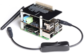
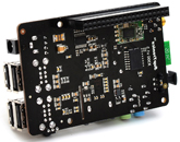
X300 SKU: EZ-0003
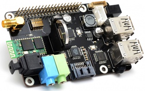
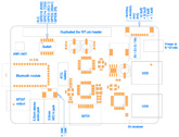
X300 EXPANSION BOARD
KEY FEATURES
| Parameter | Value |
|---|---|
| Input Voltage | 6V to 18Vdc converted to 5V, 4A via step-down DC/DC converter to power the Raspberry Pi |
| SATA | Allows you to connect SATA devices to your Raspberry Pi |
| Audio | 3.5mm MIC in jack
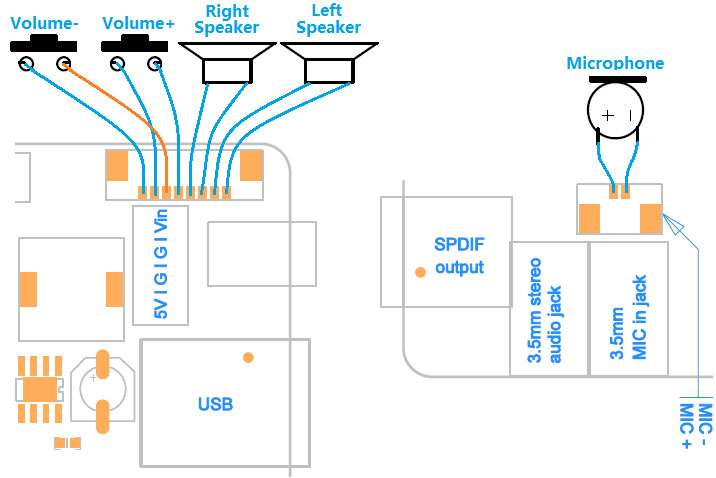
- 3.5mm stereo audio jack - SPDIF output - Audio IO connector (Microphone input and stereo audio amplifier 3.3Wx2) |
| Wireless | WiFi (IEEE 802.11b/g/n) with external antenna
- IR sensor (38KHz) - Bluetooth serial communication |
| USB Storage | Self-powered USB hub with 3 ports |
| Real-time clock (RTC) | Based on DS3231SN with included CR2032 battery |
| Misc | Power output socket
- Camera flex slot so camera can still be used with the expansion board attached - DIP switch to remove connection from RPi’s pin header - Directly connected on top of the Raspberry Pi using the board GPIO header pins - No wiring nor soldering is required - Duplicated the 40-pin header of the R-Pi in order to support existing expansion boards - Suitable for Raspberry Pi Model B+, Raspberry pi 2 Model B and Raspberry Pi 3 Model B NEW! |
| Dimensions | 85 x 56mm (Same size as Raspberry Pi) |
PACKING LIST
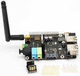
- 1 x X300 expansion board
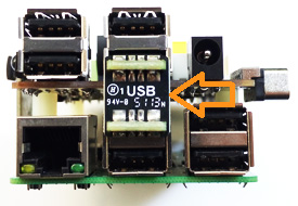
- 1 x USB adapter
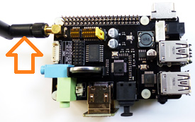
- 1 x 2.4GHz WIFI antenna
- 4 x nylon spacers (M3 x 20mm)
- 8 x nylon screws (M3 x 6mm)
QUICK START GUIDE
- A. Fitting the expansion board
- B. Operation system
- C. Power supply
- D. Microphone input and audio output
- E. Audio input and output interface
- F. Setting RTC time
- G. Testing the IR receiver
- H. SATA port
- I. Bluetooth serial communication
- A. FITTING THE EXPANSION BOARD
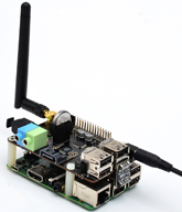
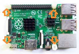
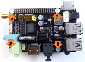
1. Push a screws up through the mounting hole on the underside of the Raspberry Pi and screw the spacer down until it is hand tight
2. Plugs the expansion board straight into your Raspberry Pi B+'s GPIO header and screw down.
3. Insert the USB adapter
4. Install the WiFi antenna
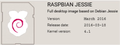
B. OPERATION SYSTEM
C. POWER SUPPLY
Xseries expansion board supplies the RPi with a regulated +5V through the GPIO header using a 2A poly-resettable (PTC) fuse.
With the wide voltage input range (6~21Vdc), the RPi can be powered from a wide variety of external sources such as batteries, 12V power adapters, solar battery sources, etc.
Recommended Power Adapter : 110~240VAC input, 12VDC 2A output
Dimension of input plug (Unit: mm)

D. MICROPHONE INPUT AND AUDIO OUTPUT
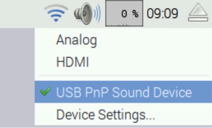
To configure X300 sound card as the default audio device.
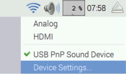
<1> Right-click the volume icon, a pop-up menu appears to allow you to select "USB PnP Sound Device".
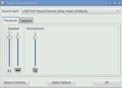
<2> Click "Device Settings..." to allow more detailed control of the X300 audio devices – you can access this either under Device Settings from the volume right-click menu or from the Preferences section of the main menu, where it is listed as Audio Device Settings.
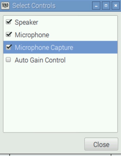
<3> From this dialog, select the device you want to control from the drop-down at the top, and then press the Select Controls button to choose which of the controls the device offers that you want to display. Pressing the Make Default button on this window has the same effect as choosing an output source in the volume right-click menu.
<4> Let's record the sound with LXterminal
pi@raspberrypi ~ $ arecord -D plughw:1,0 -f cd test.wav
<5> Press Ctrl + C to abort recording
<6> Playback the recording with aplay
pi@raspberrypi ~ $ aplay test.wav
E. AUDIO INPUT AND OUTPUT INTERFACE
F. SETTING RTC TIME
This page details how to setup the RTC Pi on the Raspbian Jessie image from http://www.raspberrypi.org/downloads
- <7> Ensure that the CR2032 coin battery was inserted into the battery holder. Using the expansion board without a battery installed may damage the RTC chip and will stop it from appearing on the I2C bus.
- <8> Follow the instructions on how to install and configure I2C on Raspbian Linux.
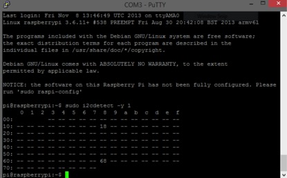
- <9> Once you have installed I2C check that the RTC Pi has been detected using:
pi@raspberrypi ~ $ sudo i2cdetect -y 1
The RTC Pi should appear on channel 68 as shown in the screen shot below.
If the RTC Pi does not appear check that the battery is installed correctly and is fully charged:
- <10> Enable I2C by running:
pi@raspberrypi ~ $ sudo nano /etc/modprobe.d/raspi-blacklist.conf
Find the I2C line where the I2c is black listed
blacklist i2c-bcm2708
Comment it out by replacing it with the line below
#blacklist i2c-bcm2708
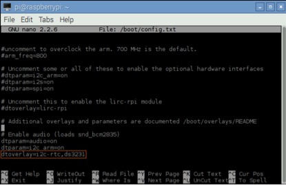
- <11> To ensure that the necessary kernel modules are loaded at boot, ensure your /boot/config.txt file has the entry below …
pi@raspberrypi ~ $  sudo nano /boot/config.txt
dtoverlay=i2c-rtc,ds3231
- <12> Save your changes by pressing Ctrl-x then Y
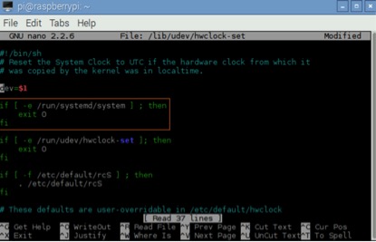
- <13> Edit /lib/udev/hwclock-set with
pi@raspberrypi ~ $ sudo nano /lib/udev/hwclock-set
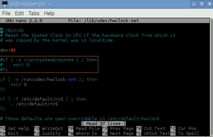
- <14> Locate the lines and edit
- <15> Comment following three lines in config.txt by adding '#' located at start of the line. (check Images below)
- <16> Save your changes by pressing Ctrl-x then Y
- <17> Reboot your Raspberry Pi
pi@raspberrypi ~ $ sudo reboot
- <18> Get the right time set on the Pi ,
pi@raspberrypi ~ $ sudo date MMDDHHMMYYYY.SS
              (MM= Month, DD= Date, HH= Hour, MM= Minute, YYYY= Year, SS= Second )
                                          example:  2013 Jan 4 , 11:39:00 , sudo date 010411392013.00
- <19> Write the system time to the expansion board,
pi@raspberrypi ~ $ sudo hwclock -w
- <20> Verify the time ,
pi@raspberrypi ~ $ sudo hwclock -r
If everything worked correctly the expansion board should be initialised on boot and the current date and time will be loaded into Linux.
