EZ-0063
GeeekNET ESP32 WROVER Development Board
ESP32-WROVER Development Board targets the high performance requirements with 4.5 MB of RAM and a dual core 240 MHz CPU.
Create Internet cameras, smart displays or Internet radios with this highly integrated ultra low power module by connecting LCDs, cameras, microphones and codecs to it.
You can even make a game boy by this module.
And you can learn python by flashing the Micropython on the chip.
ESP32 can perform as a complete standalone system or as a slave device to a host MCU.
Reducing communication stack overhead on the main application processor.
ESP32 can interface with other systems to provide Wi-Fi and Bluetooth functionality through the SPI / SDIO or I2C / UART interfaces.
ESP32 is highly-integrated with in-built antenna switches, RF balun, power amplifier, low-noise receive amplifier, filters, and power management modules.
ESP32 adds priceless functionality and versatility to your applications with minimal Printed Circuit Board (PCB) area requirements.
Engineered for mobile devices, wearable electronics and IoT applications,
ESP32 achieves ultra-low power consumption with a combination of several types of proprietary software.
The state-of-the-art power saving features include fine resolution clock gating, power modes, and dynamic power scaling.
ESP32 is capable of functioning reliably in industrial environments with an operating temperature ranging from -40°C to +125°C.
Powered by advanced calibration circuitries, ESP32 can dynamically remove external circuit imperfections or adapt to changes in external conditions.
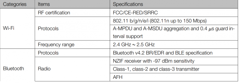
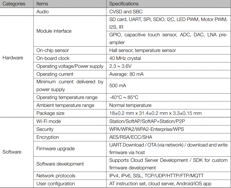
Specifications
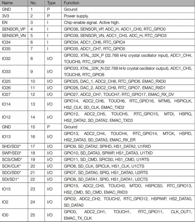
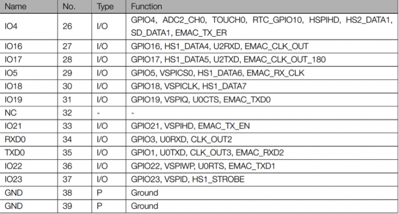
Pin definitions
- Pin Layout
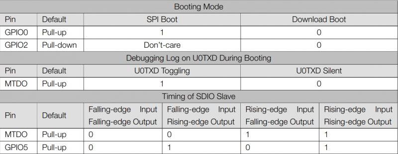
Strapping Pins
Please refer to Chapter 6 ESP32-WROVER schematics. ESP32 has five strapping pins:
- MTDI
- GPIO0
- GPIO2
- MTDO
- GPIO5
Software can read the value of these five bits from the register ”GPIO_STRAPPING”.
During the chip power-on reset, the latches of the strapping pins sample the voltage level as strapping bits of ”0”
or ”1”, and hold these bits until the chip is powered down or shut down. The strapping bits configure the device
boot mode, the operating voltage of VDD_SDIO and other system initial settings.
Each strapping pin is connected with its internal pull-up/pull-down during the chip reset. Consequently, if a strapping
pin is unconnected or the connected external circuit is high-impendence, the internal weak pull-up/pull-down
will determine the default input level of the strapping pins.
To change the strapping bit values, users can apply the external pull-down/pull-up resistances, or apply the host
MCU’s GPIOs to control the voltage level of these pins when powering on ESP32.
After reset, the strapping pins work as the normal functions pins.
Refer to Table 4 for detailed boot modes configuration by strapping pins.
