D-0006: Difference between revisions
Jump to navigation
Jump to search
m (Yoyojacky moved page PCF8574T LCD Driver Board SKU: D-0006 to D-0006) |
|||
| (4 intermediate revisions by the same user not shown) | |||
| Line 17: | Line 17: | ||
==Gallery== | ==Gallery== | ||
{| | |||
|[[File:D 0006 1.jpg|left|320px]] | |||
|[[File:D 0006 2.jpg|none|320px]] | |||
|[[File:D 0006 4.jpg|none|320px]] | |||
|} | |||
===Dimenssion=== | |||
[[File:D 0006 6.jpg|left|500px]] | |||
<br style="clear:both;"> | |||
==Package Includes== | ==Package Includes== | ||
* 1 x PCF8574T LCD Driver Board | |||
==Reference== | ==Reference== | ||
* PCF8574T Chip Datasheet: [[ File:PCF8574T Datasheet.pdf ]] | * PCF8574T Chip Datasheet: [[ File:PCF8574T Datasheet.pdf ]] | ||
| Line 79: | Line 90: | ||
</pre> | </pre> | ||
===Python Demo Code=== | ===Python Demo Code=== | ||
* Copy following code and save it as: <font color=red>I2C_LCD_driver.py</font> | |||
<pre> | |||
# -*- coding: utf-8 -*- | |||
# Original code found at: | |||
# https://gist.github.com/DenisFromHR/cc863375a6e19dce359d | |||
""" | |||
Compiled, mashed and generally mutilated 2014-2015 by Denis Pleic | |||
Made available under GNU GENERAL PUBLIC LICENSE | |||
# Modified Python I2C library for Raspberry Pi | |||
# as found on http://www.recantha.co.uk/blog/?p=4849 | |||
# Joined existing 'i2c_lib.py' and 'lcddriver.py' into a single library | |||
# added bits and pieces from various sources | |||
# By DenisFromHR (Denis Pleic) | |||
# 2015-02-10, ver 0.1 | |||
""" | |||
# i2c bus (0 -- original Pi, 1 -- Rev 2 Pi) | |||
# I2CBUS = 0 | |||
I2CBUS = 1 | |||
# LCD Address | |||
#ADDRESS = 0x3f | |||
ADDRESS = 0x27 | |||
import smbus | |||
from time import sleep | |||
class i2c_device: | |||
def __init__(self, addr, port=I2CBUS): | |||
self.addr = addr | |||
self.bus = smbus.SMBus(port) | |||
# Write a single command | |||
def write_cmd(self, cmd): | |||
self.bus.write_byte(self.addr, cmd) | |||
sleep(0.0001) | |||
# Write a command and argument | |||
def write_cmd_arg(self, cmd, data): | |||
self.bus.write_byte_data(self.addr, cmd, data) | |||
sleep(0.0001) | |||
# Write a block of data | |||
def write_block_data(self, cmd, data): | |||
self.bus.write_block_data(self.addr, cmd, data) | |||
sleep(0.0001) | |||
# Read a single byte | |||
def read(self): | |||
return self.bus.read_byte(self.addr) | |||
# Read | |||
def read_data(self, cmd): | |||
return self.bus.read_byte_data(self.addr, cmd) | |||
# Read a block of data | |||
def read_block_data(self, cmd): | |||
return self.bus.read_block_data(self.addr, cmd) | |||
# commands | |||
LCD_CLEARDISPLAY = 0x01 | |||
LCD_RETURNHOME = 0x02 | |||
LCD_ENTRYMODESET = 0x04 | |||
LCD_DISPLAYCONTROL = 0x08 | |||
LCD_CURSORSHIFT = 0x10 | |||
LCD_FUNCTIONSET = 0x20 | |||
LCD_SETCGRAMADDR = 0x40 | |||
LCD_SETDDRAMADDR = 0x80 | |||
# flags for display entry mode | |||
LCD_ENTRYRIGHT = 0x00 | |||
LCD_ENTRYLEFT = 0x02 | |||
LCD_ENTRYSHIFTINCREMENT = 0x01 | |||
LCD_ENTRYSHIFTDECREMENT = 0x00 | |||
# flags for display on/off control | |||
LCD_DISPLAYON = 0x04 | |||
LCD_DISPLAYOFF = 0x00 | |||
LCD_CURSORON = 0x02 | |||
LCD_CURSOROFF = 0x00 | |||
LCD_BLINKON = 0x01 | |||
LCD_BLINKOFF = 0x00 | |||
# flags for display/cursor shift | |||
LCD_DISPLAYMOVE = 0x08 | |||
LCD_CURSORMOVE = 0x00 | |||
LCD_MOVERIGHT = 0x04 | |||
LCD_MOVELEFT = 0x00 | |||
# flags for function set | |||
LCD_8BITMODE = 0x10 | |||
LCD_4BITMODE = 0x00 | |||
LCD_2LINE = 0x08 | |||
LCD_1LINE = 0x00 | |||
LCD_5x10DOTS = 0x04 | |||
LCD_5x8DOTS = 0x00 | |||
# flags for backlight control | |||
LCD_BACKLIGHT = 0x08 | |||
LCD_NOBACKLIGHT = 0x00 | |||
En = 0b00000100 # Enable bit | |||
Rw = 0b00000010 # Read/Write bit | |||
Rs = 0b00000001 # Register select bit | |||
class lcd: | |||
#initializes objects and lcd | |||
def __init__(self): | |||
self.lcd_device = i2c_device(ADDRESS) | |||
self.lcd_write(0x03) | |||
self.lcd_write(0x03) | |||
self.lcd_write(0x03) | |||
self.lcd_write(0x02) | |||
self.lcd_write(LCD_FUNCTIONSET | LCD_2LINE | LCD_5x8DOTS | LCD_4BITMODE) | |||
self.lcd_write(LCD_DISPLAYCONTROL | LCD_DISPLAYON) | |||
self.lcd_write(LCD_CLEARDISPLAY) | |||
self.lcd_write(LCD_ENTRYMODESET | LCD_ENTRYLEFT) | |||
sleep(0.2) | |||
# clocks EN to latch command | |||
def lcd_strobe(self, data): | |||
self.lcd_device.write_cmd(data | En | LCD_BACKLIGHT) | |||
sleep(.0005) | |||
self.lcd_device.write_cmd(((data & ~En) | LCD_BACKLIGHT)) | |||
sleep(.0001) | |||
def lcd_write_four_bits(self, data): | |||
self.lcd_device.write_cmd(data | LCD_BACKLIGHT) | |||
self.lcd_strobe(data) | |||
# write a command to lcd | |||
def lcd_write(self, cmd, mode=0): | |||
self.lcd_write_four_bits(mode | (cmd & 0xF0)) | |||
self.lcd_write_four_bits(mode | ((cmd << 4) & 0xF0)) | |||
# write a character to lcd (or character rom) 0x09: backlight | RS=DR< | |||
# works! | |||
def lcd_write_char(self, charvalue, mode=1): | |||
self.lcd_write_four_bits(mode | (charvalue & 0xF0)) | |||
self.lcd_write_four_bits(mode | ((charvalue << 4) & 0xF0)) | |||
# put string function with optional char positioning | |||
def lcd_display_string(self, string, line=1, pos=0): | |||
if line == 1: | |||
pos_new = pos | |||
elif line == 2: | |||
pos_new = 0x40 + pos | |||
elif line == 3: | |||
pos_new = 0x14 + pos | |||
elif line == 4: | |||
pos_new = 0x54 + pos | |||
self.lcd_write(0x80 + pos_new) | |||
for char in string: | |||
self.lcd_write(ord(char), Rs) | |||
# clear lcd and set to home | |||
def lcd_clear(self): | |||
self.lcd_write(LCD_CLEARDISPLAY) | |||
self.lcd_write(LCD_RETURNHOME) | |||
# define backlight on/off (lcd.backlight(1); off= lcd.backlight(0) | |||
def backlight(self, state): # for state, 1 = on, 0 = off | |||
if state == 1: | |||
self.lcd_device.write_cmd(LCD_BACKLIGHT) | |||
elif state == 0: | |||
self.lcd_device.write_cmd(LCD_NOBACKLIGHT) | |||
# add custom characters (0 - 7) | |||
def lcd_load_custom_chars(self, fontdata): | |||
self.lcd_write(0x40); | |||
for char in fontdata: | |||
for line in char: | |||
self.lcd_write_char(line) | |||
</pre> | |||
* Create a file named: lcd1602.py and paste following code: | |||
<pre> | |||
import I2C_LCD_driver | |||
from time import * | |||
mylcd = I2C_LCD_driver.lcd() | |||
# There are 16 character that you can put on the screen and 2 lines avaliable. | |||
mylcd.lcd_display_string("00000000000000000", 1, 0) | |||
mylcd.lcd_display_string("00000000000000000", 2, 0) | |||
</pre> | |||
* Run it. | |||
<pre> | |||
python lcd1602.py | |||
</pre> | |||
==Application Scenario== | |||
* Control-Any-Devices-Using-Raspberry-PI-and-PCF8574: [ https://www.instructables.com/id/Control-Any-Devices-Using-Raspberry-PI-and-PCF8574/ ] | |||
* I2C-1602-LCD: [https://github.com/VeggieVampire/I2C-1602-LCD] | |||
==Keywords== | |||
* PCF8574T, LCD1602, driver board, LCD driver board | |||
Latest revision as of 18:50, 27 August 2021
PCF8574T LCD Driver Board

Description
The PCF8574T IO Expansion Board is used as remote 8-bit I/O expander for I2C-bus.
Up to 8 PCF8574T IO Expansion Board can be connected to the I2C-bus, providing up to 64 I/O ports.
The PCF8574T IO Expansion Board features allowing the use of multi module connected to the I2C bus at the same time by connecting the pinheader and connector.
There is a small potentiometer onboard, which can adjust the backlight of LCD1602 or LCD2004, and a jumper cap to control the switch of the LED light.
Features
- PCF8574T Chip
- I2C interface
- 8-bit parallel port
- Potentiometer Backlight control
- LED jumper switch
- Default I2C address: 0x27
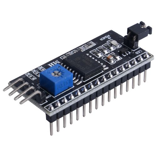
Gallery
|
 |
 |
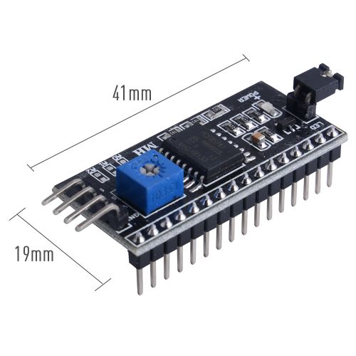
Dimenssion

Package Includes
- 1 x PCF8574T LCD Driver Board
Reference
- PCF8574T Chip Datasheet: File:PCF8574T Datasheet.pdf
- WiringPi: [ http://wiringpi.com/extensions/i2c-pcf8574/ ]
- telecnatron:[ https://telecnatron.com/articles/Utility-To-Control-1602-LCD-On-Raspberry-Pi-Via-A-PCF8574-I2C-Backpack-Module/index.html]
- Circuitbasics:[ https://www.circuitbasics.com/raspberry-pi-i2c-lcd-set-up-and-programming/ ]
Demo Code For Handle PCF8574T
- Download and reinstall wiringPi liberary
sudo apt -y purge wiringpi
hash -r
cd /tmp
wget https://project-downloads.drogon.net/wiringpi-latest.deb
sudo dpkg -i wiringpi-latest.deb
- C++ language
#include <stdio.h>
#include <time.h>
#include <string>

#include <wiringPi.h>
#include <pcf8574.h>

using namespace std;
int main (int argc, char *argv[]){
	printf("Raspberry Pi initializing...\n");

        wiringPiSetup();
	pcf8574Setup(100, 0x38);

	for (int i = 0; i < 8; ++i){
    		pinMode(100 + i, OUTPUT);
	}

        int b=0;
        while( 1==1 ){
                printf("LOOP %u\n", b);
                for (int i = 0; i < 8; ++i){
                    digitalWrite(100 + i, i==b ? 0 : 1);
                }
                b++;
		if( b >= 8 ) b=0;
		delay(1000);

	}

	delay(1000);
	digitalWrite(100 + 0, 0);

	delay(1000);
        digitalWrite(100 + 0, 1);

	return 0;
}
- Compile and run it.
g++ pcf8574.cpp -o pcf8574 -lwiringPi -std=c++11
./pcf8574
Python Demo Code
- Copy following code and save it as: I2C_LCD_driver.py
# -*- coding: utf-8 -*-
# Original code found at:
# https://gist.github.com/DenisFromHR/cc863375a6e19dce359d

"""
Compiled, mashed and generally mutilated 2014-2015 by Denis Pleic
Made available under GNU GENERAL PUBLIC LICENSE

# Modified Python I2C library for Raspberry Pi
# as found on http://www.recantha.co.uk/blog/?p=4849
# Joined existing 'i2c_lib.py' and 'lcddriver.py' into a single library
# added bits and pieces from various sources
# By DenisFromHR (Denis Pleic)
# 2015-02-10, ver 0.1

"""

# i2c bus (0 -- original Pi, 1 -- Rev 2 Pi)
# I2CBUS = 0
I2CBUS = 1

# LCD Address
#ADDRESS = 0x3f
ADDRESS = 0x27

import smbus
from time import sleep

class i2c_device:
   def __init__(self, addr, port=I2CBUS):
      self.addr = addr
      self.bus = smbus.SMBus(port)

# Write a single command
   def write_cmd(self, cmd):
      self.bus.write_byte(self.addr, cmd)
      sleep(0.0001)

# Write a command and argument
   def write_cmd_arg(self, cmd, data):
      self.bus.write_byte_data(self.addr, cmd, data)
      sleep(0.0001)

# Write a block of data
   def write_block_data(self, cmd, data):
      self.bus.write_block_data(self.addr, cmd, data)
      sleep(0.0001)

# Read a single byte
   def read(self):
      return self.bus.read_byte(self.addr)

# Read
   def read_data(self, cmd):
      return self.bus.read_byte_data(self.addr, cmd)

# Read a block of data
   def read_block_data(self, cmd):
      return self.bus.read_block_data(self.addr, cmd)


# commands
LCD_CLEARDISPLAY = 0x01
LCD_RETURNHOME = 0x02
LCD_ENTRYMODESET = 0x04
LCD_DISPLAYCONTROL = 0x08
LCD_CURSORSHIFT = 0x10
LCD_FUNCTIONSET = 0x20
LCD_SETCGRAMADDR = 0x40
LCD_SETDDRAMADDR = 0x80

# flags for display entry mode
LCD_ENTRYRIGHT = 0x00
LCD_ENTRYLEFT = 0x02
LCD_ENTRYSHIFTINCREMENT = 0x01
LCD_ENTRYSHIFTDECREMENT = 0x00

# flags for display on/off control
LCD_DISPLAYON = 0x04
LCD_DISPLAYOFF = 0x00
LCD_CURSORON = 0x02
LCD_CURSOROFF = 0x00
LCD_BLINKON = 0x01
LCD_BLINKOFF = 0x00

# flags for display/cursor shift
LCD_DISPLAYMOVE = 0x08
LCD_CURSORMOVE = 0x00
LCD_MOVERIGHT = 0x04
LCD_MOVELEFT = 0x00

# flags for function set
LCD_8BITMODE = 0x10
LCD_4BITMODE = 0x00
LCD_2LINE = 0x08
LCD_1LINE = 0x00
LCD_5x10DOTS = 0x04
LCD_5x8DOTS = 0x00

# flags for backlight control
LCD_BACKLIGHT = 0x08
LCD_NOBACKLIGHT = 0x00

En = 0b00000100 # Enable bit
Rw = 0b00000010 # Read/Write bit
Rs = 0b00000001 # Register select bit

class lcd:
   #initializes objects and lcd
   def __init__(self):
      self.lcd_device = i2c_device(ADDRESS)

      self.lcd_write(0x03)
      self.lcd_write(0x03)
      self.lcd_write(0x03)
      self.lcd_write(0x02)

      self.lcd_write(LCD_FUNCTIONSET | LCD_2LINE | LCD_5x8DOTS | LCD_4BITMODE)
      self.lcd_write(LCD_DISPLAYCONTROL | LCD_DISPLAYON)
      self.lcd_write(LCD_CLEARDISPLAY)
      self.lcd_write(LCD_ENTRYMODESET | LCD_ENTRYLEFT)
      sleep(0.2)


   # clocks EN to latch command
   def lcd_strobe(self, data):
      self.lcd_device.write_cmd(data | En | LCD_BACKLIGHT)
      sleep(.0005)
      self.lcd_device.write_cmd(((data & ~En) | LCD_BACKLIGHT))
      sleep(.0001)

   def lcd_write_four_bits(self, data):
      self.lcd_device.write_cmd(data | LCD_BACKLIGHT)
      self.lcd_strobe(data)

   # write a command to lcd
   def lcd_write(self, cmd, mode=0):
      self.lcd_write_four_bits(mode | (cmd & 0xF0))
      self.lcd_write_four_bits(mode | ((cmd << 4) & 0xF0))

   # write a character to lcd (or character rom) 0x09: backlight | RS=DR<
   # works!
   def lcd_write_char(self, charvalue, mode=1):
      self.lcd_write_four_bits(mode | (charvalue & 0xF0))
      self.lcd_write_four_bits(mode | ((charvalue << 4) & 0xF0))

   # put string function with optional char positioning
   def lcd_display_string(self, string, line=1, pos=0):
    if line == 1:
      pos_new = pos
    elif line == 2:
      pos_new = 0x40 + pos
    elif line == 3:
      pos_new = 0x14 + pos
    elif line == 4:
      pos_new = 0x54 + pos

    self.lcd_write(0x80 + pos_new)

    for char in string:
      self.lcd_write(ord(char), Rs)

   # clear lcd and set to home
   def lcd_clear(self):
      self.lcd_write(LCD_CLEARDISPLAY)
      self.lcd_write(LCD_RETURNHOME)

   # define backlight on/off (lcd.backlight(1); off= lcd.backlight(0)
   def backlight(self, state): # for state, 1 = on, 0 = off
      if state == 1:
         self.lcd_device.write_cmd(LCD_BACKLIGHT)
      elif state == 0:
         self.lcd_device.write_cmd(LCD_NOBACKLIGHT)

   # add custom characters (0 - 7)
   def lcd_load_custom_chars(self, fontdata):
      self.lcd_write(0x40);
      for char in fontdata:
         for line in char:
            self.lcd_write_char(line)
- Create a file named: lcd1602.py and paste following code:
import I2C_LCD_driver
from time import *

mylcd = I2C_LCD_driver.lcd()
# There are 16 character that you can put on the screen and 2 lines avaliable.
mylcd.lcd_display_string("00000000000000000", 1, 0)
mylcd.lcd_display_string("00000000000000000", 2, 0)
- Run it.
python lcd1602.py
Application Scenario
- Control-Any-Devices-Using-Raspberry-PI-and-PCF8574: [ https://www.instructables.com/id/Control-Any-Devices-Using-Raspberry-PI-and-PCF8574/ ]
- I2C-1602-LCD: [1]
Keywords
- PCF8574T, LCD1602, driver board, LCD driver board