EP-0076: Difference between revisions
Jump to navigation
Jump to search
| Line 86: | Line 86: | ||
---- | ---- | ||
* You will see a chart like following picture:<br> | * You will see a chart like following picture:<br> | ||
[[File:Ads1115-result.jpg|left| | [[File:Ads1115-result.jpg|left|500px]] | ||
<br style="clear:both;"> | <br style="clear:both;"> | ||
---- | ---- | ||
Revision as of 16:29, 18 November 2016
RPI-ADS1115-ADC-Module
 |
 |
 |
 |
Description
The ADS1115 are precision analog-to-digital converters (ADCs) with 16 bits of resolution offered in an ultra-small,
leadless QFN-10 package or an MSOP-10 package.
The ADS1115 are designed with precision, power, and ease of implementation in mind.
The ADS1115  feature an onboard reference and oscillator.
Data are transferred via an I2C-compatible serial interface, four I2C slave addresses can be selected.
The ADS1115 operate from a single power supply ranging from 2.0V to 5.5V.
The ADS1115 can perform conversions at rates up to 860 samples per second (SPS).
An onboard PGA is available on the ADS1114 and ADS1115 that offers input ranges from the supply to as low as ±256mV,
allowing both large and small signals to be measured with high resolution.
The ADS1115 also features an input multiplexer (MUX) that provides two differential or four single-ended inputs.
The ADS1115 operate either in continuous conversion mode or a single-shot mode that automatically powers down
after a conversion and greatly reduces current consumption during idle periods.
The ADS1115 are specified from –40°C to +125°C.
Features
| Parameters | Values |
|---|---|
| ULTRA-SMALL QFN PACKAGE: | 2mm × 1,5mm × 0,4mm |
| WIDE SUPPLY RANGE: | 2.0V to 5.5V |
| LOW CURRENT CONSUMPTION: | Continuous Mode: Only 150μA
Single-Shot Mode: Auto Shut-Down |
| PROGRAMMABLE DATA RATE: | 8SPS to 860SPS |
| INTERNAL LOW-DRIFT: | VOLTAGE REFERENCE |
| INTERNAL OSCILLATOR | Available |
| INTERNAL PGA | Available |
| I2C™ INTERFACE: | Pin-Selectable Addresses |
| FOUR SINGLE-ENDED OR TWO DIFFERENTIAL INPUTS | ADS1115 |
| PROGRAMMABLE COMPARATOR | ADS1115 |
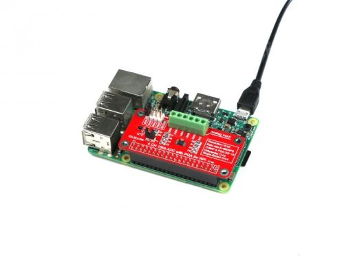
How to wire up
Just Plug into GPIO with this module.
- NOTE: Please be ware of the No.1 Pin is fit for your GPIO No.1 Pin.

How to get analog data
- All steps are available that we've consumed that you have already flashed the newest image file into your TF card, and your RaspberryPi is powered on.
- Modify /boot/config.txt file and add those parameters to enable ADC module's driver:
sudo vim.tiny /boot/config.txt
   device_tree=bcm2710-rpi-3-b.dtb
   dtparam=i2c_arm=on
   dtoverlay=ads1015
Save it and reboot your raspberry Pi.
- Python code to use the ADS1015 and ADS1115 analog to digital converters with a Raspberry Pi or BeagleBone black.
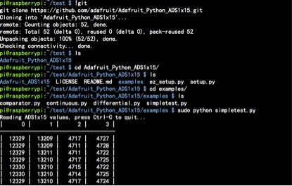
- To install the library from source (recommended) run the following commands on a Raspberry Pi or other Debian-based OS system:
sudo apt-get install git build-essential python-dev
cd ~
git clone https://github.com/adafruit/Adafruit_Python_ADS1x15.git
cd Adafruit_Python_ADS1x15
sudo python setup.py install
- Alternatively you can install from pip with:
sudo pip install adafruit-ads1x15
- Change your work directory to Adafruit_Python_ADS1x15/example as following command:
cd ~/Adafruit_Python_ADS1x15/examples
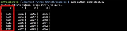
sudo python simpletest.py
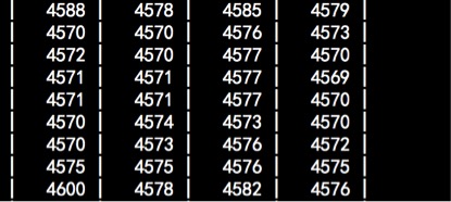
- You will see a chart like following picture:

- Do not panic when you see this picture:

- Remove the jumper from NTC_EN to AIN0, it will be back to normal.

Official Documents
- Datasheet:
FAQ
- Question:
- Answer: